A320TECHNICAL TRAINING MANUAL-PNEUMATIC技术培训手册-气动
PNEUMATIC SYSTEM COMPONENT LOCATION (2)
SYSTEM OVERVIEW
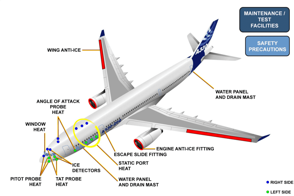
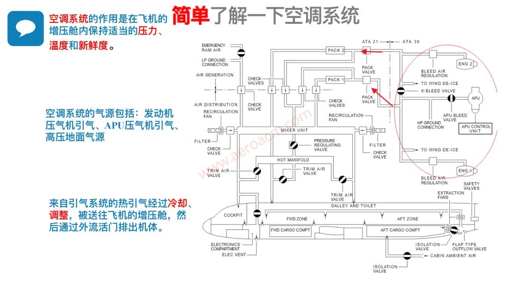
The Pneumatic system is used to supply High Pressure (HP) air for air conditioning, pressurization, Fuel Tank Inerting System (FTIS), engine start and anti-icing. HP air can be supplied from the two engines, the APU or an external ground source.
系统概述
气动系统用于为空调、增压、油箱惰性系统 (FTIS)、发动机启动和防冰提供高压 (HP) 空气。高压空气可由两台发动机、APU 或外部地面源提供。
ENGINE BLEED
The engine bleed air receives pressure regulation and temperature regulation before it is supplied to the pneumatic system. Air is bled from two engine High Pressure Compressor (HPC) stages: the Intermediate Pressure (IP) stage and the HP stage.
The High Pressure Bleed Valve (HPV) supplies air to the system when the engines are at low power. When the IP bleed is sufficient, the HPV closes.
The Pressure Regulating Valve (PRV) is installed in the duct downstream of the IP and HP bleed valves, and pneumatically regulates the downstream pressure. Each Bleed Monitoring Computer (BMC) monitors the system pressure and will stop the engine bleed if the pressure is too high. An Overpressure Valve (OPV) is also installed downstream from the bleed valve as a protection of the system if the pressure is too high.
The temperature of the engine bleed air is regulated to a maximum value. The hot bleed air goes through an air-to-air heat exchanger called the precooler. Fan discharge air, modulated by the Fan Air Valve (FAV), is blown across the pre-cooler to keep the temperature within limits.
发动机引气
发动机引气在供应给气动系统之前会接受压力调节和温度调节。引气来自两个发动机高压压缩机 (HPC) 级:中间压力 (IP) 级和高压级。
当发动机处于低功率状态时,高压引气活门 (HPV) 向系统供气。当 IP 引气足够时,HPV 关闭。
压力调节活门 (PRV) 安装在 IP 和 HP 引气活门下游的管道中,以气动方式调节下游压力。每个引气监控计算机 (BMC) 都监控系统压力,如果压力过高,将停止发动机引气。此外,还在引气活门下游安装了一个超压活门 (OPV),以便在压力过高时保护系统。
发动机引气的温度被调节到最高值。热的引气通过一个名为预冷却器的空气-空气热交换器。由风扇空气活门 (FAV) 调节的风扇排出空气吹过预冷却器,使温度保持在限定范围内。
APU BLEED/EXTERNAL AIR
The left and right bleed systems are connected by a crossbleed duct.
A crossbleed valve is used for their interconnection or isolation.
The APU can also be used for bleed air supply. This is usually done on the ground for air conditioning and for engine start.
But APU BLEED air can also be used in flight, in relation to the altitude. The altitude can be different for each aircraft. These altitude limits are given by the manufacturer. The APU bleed supply is connected to the left side of the crossbleed duct.
On the ground, a HP ground power unit can be connected to the left side pneumatic system. The right side can be supplied by opening the crossbleed valve.
APU引气/外部空气
左侧和右侧引气系统通过交叉引气管连接。
交输活门用于它们之间的连接或隔离。
APU 也可用于引气。这通常在地面进行,用于空调和发动机启动。
但 APU 引气也可在飞行中根据飞行高度使用。每架飞机的飞行高度可能不同。这些高度限制由制造商提供。APU 引气供应连接到交叉引气管的左侧。
在地面上,可将 HP 地面动力装置连接至左侧气动系统。右侧可通过打开交输活门进行供气。
![图片[1]-A320-36气源【系统原理】-航修札记](https://aeroacm.cn/wp-content/uploads/2025/02/word-image-2696-1.png)
PNEUMATIC SYSTEM COMPONENT LOCATION (2)
SYSTEM OVERVIEW (continued)
LEAK DETECTION
Leak detection loops are installed along the hot air supply ducts of the pneumatic system and are connected to the BMCs. The leak detection system is organized into three loops. Here are the loops and the protected areas:
– PYLON: the pre-cooler outlet area,
– WING: wing leading edge and belly fairing,
– APU: APU aft supply duct (left hand side of the fuselage) from APU firewall to wheel well area.
泄漏检测
泄漏检测回路沿气动系统的热风供应管道安装,并与 BMC 相连。泄漏检测系统分为三个环路。以下是环路和保护区域:
– 吊架:预冷器出口区域、
– 机翼:机翼前缘和腹部整流罩、
– APU:从 APU 防火墙到轮井区域的 APU后部供应管道(机身左侧)。
![图片[2]-A320-36气源【系统原理】-航修札记](https://aeroacm.cn/wp-content/uploads/2025/02/word-image-2696-2.png)
PNEUMATIC SYSTEM COMPONENT LOCATION (2)
COMPONENT LOCATION
The primary components of the pneumatic system are installed on the engines and in the pylons.
组件位置
气动系统的主要部件安装在发动机和吊架上。
PRESSURE REGULATION COMPONENTS
The pressure regulation components are on the engines:
– the Engine High Pressure Valve (HPV),
– the Engine BLEED PRV,
– the OPV.
压力调节组件
压力调节组件安装在发动机上:
– 发动机高压活门 (HPV)、
– 发动机引气 PRV、
– OPV.
TEMPERATURE REGULATION COMPONENTS
The temperature regulation components are on the engines and in the pylons:
– the FAV,
– the Precooler.
温度调节组件
温度调节组件位于发动机和吊架上:
– FAV、
– 预冷器。
![图片[3]-A320-36气源【系统原理】-航修札记](https://aeroacm.cn/wp-content/uploads/2025/02/word-image-2696-3.png)
![图片[4]-A320-36气源【系统原理】-航修札记](https://aeroacm.cn/wp-content/uploads/2025/02/word-image-2696-4.png)
PNEUMATIC SYSTEM COMPONENT LOCATION (2)
COMPONENT LOCATION (continued)
OTHER COMPONENTS
The crossbleed valve is in the forward section of the lower fuselage belly fairing area.
Get access to the HP ground connector through a small access door which is on the lower fuselage belly fairing.
The APU bleed valve is on the APU.
The APU supply duct is installed along the left hand side of the fuselage to the wheel well area.
It then goes across the aircraft centerline and continues forward to be connected to the crossbleed duct in the forward belly fairing area.
其他部件
交输活门位于下机身腹部整流罩的前部。
通过下机身腹部整流罩上的一个小接近门进入 HP 接地连接器。
APU 引气活门位于 APU 上。
APU 供应管道沿机身左侧安装到轮井区域。
然后穿过飞机中心线继续向前,连接到前机腹整流罩区域的交叉引气管。
![图片[5]-A320-36气源【系统原理】-航修札记](https://aeroacm.cn/wp-content/uploads/2025/02/word-image-2696-5.png)
PNEUMATIC SYSTEM CONTROL & INDICATING (2)
LOCATE CONTROL/INDICATING IN COCKPIT
BLEED AIR SUPPLY ON GROUND
BLEED SUPPLY FROM ENGINES
驾驶舱内的控制/指示装置位置
在地面引气
从发动机引气
ENGINE BLEED SYSTEM DESCRIPTION (3)
B2 SCOPE
CAUTION: MODULE TAGGED B2 SCOPE. BE AWARE THAT ONLY AVIONICS/ELECTRICAL TOPICS SHOULD BE LEARNED FOR A T2 COURSE.
B2 范围
注意:模块标记为 B2 范围。请注意,T2 课程只应学习航空电子/电气主题。
GENERAL
The engine air bleed pressure is pneumatically regulated by the High Pressure (HP) Valve (VLV) when air is supplied by the HP stage, or by the Pressure Regulating Valve (PRV) when the air is supplied by the Intermediate Pressure (IP) stage. The pressure regulation system is monitored by two Bleed Monitoring Computers (BMCs).
通用
由高压 (HP) 级供气时,发动机引气压力由高压 (HP) 活门 (VLV) 进行气动调节;由中压 (IP) 级供气时,发动机引气压力由压力调节活门 (PRV) 进行调节。压力调节系统由两台引气监控计算机 (BMC) 监控。
HP VALVE
Switching between IP and HP is done pneumatically when the IP stage pressure is not sufficient (engine at low speed). The HP VLV pneumatically regulates the air supply between 8 and 36 psi. The HP VLV is forced to close when the PRV is closed via the PRV/HP VLV sense line. In flight, the Electronic Engine Control (EEC) for IAE V2500-A5 engines maintains the HP VLV closed.
When the solenoid is de-energized, the opening of the HP VLV is not inhibited. The solenoid will be energized by the EEC when:
– the engine is above idle, the pressure PS3 is greater than 110 psi for the single aisle family IAE V2500-A5 engine,
– the Wing Anti-Ice (WAI) is OFF,
– the altitude is over 15,000 ft,
– the pack configuration is normal.
HP 活门
当 IP 级压力不足时(发动机低速运转),可通过气动方式在 IP 和 HP 之间进行切换。HP VLV 可在 8 至 36 psi 之间对供气进行气动调节。当 PRV 通过 PRV/HP VLV 感应管路关闭时,HP VLV 将被迫关闭。在飞行过程中,用于 IAE V2500-A5 发动机的发动机电子控制器 (EEC) 会保持 HP VLV 关闭。
当电磁阀断电时,不会抑制 HP VLV 的打开。当出现以下情况时,电磁阀将由 EEC 接通
– 发动机超过怠速,单通道系列 IAE V2500-A5 发动机的 PS3 压力大于 110 psi、
– 机翼防冰 (WAI) 关闭、
– 海拔高度超过 15,000 英尺、
– pack配置正常。
IP CHECK VALVE
The IP check valve protects the IP stage from reverse flow when the HP VLV is open.
IP 活门
当 HP VLV 打开时,IP 单向活门保护 IP 级不发生逆流。
PRV/CONTROL SOLENOID
The PRV pneumatically regulates the bleed pressure around 44 psi. A thermal fuse causes the valve to close in case of engine fire at 450°C (842°F). The PRV is pneumatically controlled by an external servo-control, the bleed pressure regulated valve control solenoid (CTL SOL), located downstream from the precooler. The control solenoid operates in two modes, pneumatic and electric, causing complete closure of the PRV. The pneumatic mode is used for:
– reverse flow protection
– the PRV is closed when a delta pressure between the precooler outlet and the PRV inlet is detected.
The electrical mode with PRV shut-off function through energization of the control solenoid is used when:
– the ENGine BLEED P/B is selected “OFF”,
– the ENGine FIRE P/B is RELEASED OUT,
The solenoid is automatically energized by the BMC in the following cases:
– over-temperature downstream of the precooler
– the heat exchanger outlet temperature sensor senses a temperature above 257°C (527°F),
– overpressure downstream of the PRV when the pressure-regulated transducer senses a pressure greater than 57 psi,
– leak detection in pylon/wing/fuselage ducts and surrounding areas,
– APU bleed valve not closed,
– corresponding starter valve not closed.
PRV/控制电磁阀
PRV 可气动调节 44 psi 左右的引气压力。当发动机在 450°C (842°F) 温度下起火时,热熔断器会使活门关闭。PRV 由一个外部伺服控制器进行气动控制,即位于预冷却器下游的放气压力调节阀控制电磁阀 (CTL SOL)。控制电磁阀在气动和电动两种模式下工作,导致 PRV 完全关闭。气动模式用于:
– 逆流保护
– 当检测到预冷却器出口和 PRV 入口之间存在压差时,PRV 关闭。
通过控制电磁阀通电实现 PRV 关闭功能的电气模式用于以下情况
– ENGine BLEED P/B 选择 “OFF(关闭)”、
– ENGine FIRE P/B 被释放、
在下列情况下,BMC 会自动启动电磁阀:
– 预冷却器下游温度过高
– 热交换器出口温度传感器检测到温度超过 257°C (527°F)、
– 当压力调节传感器检测到压力超过 57 psi 时,PRV 下游出现超压、
– 吊架/机翼/机身管道和周围区域的泄漏检测、
– APU 引气活门未关闭、
– 相应的启动器活门未关闭。
OPV
The Overpressure Valve (OPV), which is normally open, closes pneumatically. The OPV starts to close at 75 psi. It is fully closed at 85 psi and opens again at around 35 psi.
OPV
超压活门 (OPV) 常开,以气动方式关闭。OPV 在 75 psi 时开始关闭。在 85 psi 时完全关闭,并在 35 psi 左右再次打开。
REGULATED PRESSURE
A transducer, connected to both BMCs, reads the regulated pressure downstream from the PRV. This pressure is indicated on the ECAM.
调节压力
连接至两个 BMC 的传感器可读取 PRV 下游的调节压力。该压力显示在 ECAM 上。
TRANSFERRED PRESSURE
A transducer, connected to the related BMC, reads the transferred pressure downstream from the High Pressure Valve (HPV). This pressure is used to monitor the PRV and the HPV.
传输压力
连接到相关 BMC 的传感器读取高压活门 (HPV) 下游的传输压力。该压力用于监控 PRV 和 HPV。
FAV/CONTROL THERMOSTAT
The Fan Air Valve (FAV) pneumatically regulates the fan airflow to the precooler for bleed air temperature regulation at 200°C (392°F). The FAV is pneumatically controlled by an external servo-control: the FAV control thermostat (CTL THERMST), located downstream from the precooler.
风扇空气活门 / 控制恒温器
风扇活门 (FAV) 以气动方式调节进入预冷却器的风扇气流,用于调节 200°C (392°F) 的引气温度。FAV 由位于预冷却器下游的外部伺服控制器气动控制:FAV 控制恒温器 (CTL THERMST)。
PRECOOLER
The precooler is an air-to-air heat exchanger.
预冷器
预冷却器是一个空气对空气热交换器。
HEAT EXCHANGER OUTLET TEMPERATURE SENSOR
The heat exchanger outlet temperature sensor, connected to both BMCs, reads the regulated temperature downstream from the precooler. This temperature is shown on the ECAM and used to monitor the system.
NOTE: If the precooler exchanger outlet temperature reaches 240°C (464°F), the BMC generates a class 2 maintenance message – “AIR BLEED” – on the ECAM STATUS page. An associated maintenance message “Thermostat (THRMST), FAV or sense line” can be seen on the PFR, or on the MCDU.
热交换器出口温度传感器
热交换器出口温度传感器连接至两个 BMC,用于读取预冷却器下游的调节温度。该温度显示在 ECAM 上,用于监控系统。
注: 如果预冷却器交换器出口温度达到 240°C (464°F),BMC 将在 ECAM STATUS 页面上生成 2 级维护信息 – “AIR BLEED”。在 PFR 或 MCDU 上可以看到相关的维护信息 “Thermostat (THRMST), FAV or sense line”。
![图片[6]-A320-36气源【系统原理】-航修札记](https://aeroacm.cn/wp-content/uploads/2025/02/word-image-2696-6.png)
APU BLEED AIR SPLY/X-BLEED SYSTEM D/O (3)
B2 SCOPE
CAUTION: MODULE TAGGED B2 SCOPE. BE AWARE THAT ONLY AVIONICS/ELECTRICAL TOPICS SHOULD BE LEARNED FOR A T2 COURSE.
B2 范围
注意:模块标记为 B2 范围。请注意,T2 课程只应学习航空电子/电气主题。
APU BLEED
The APU bleed air supplies the pneumatic system, through the APU bleed valve, if the APU is running.
The Bleed Load Valve for the APU GTCP 36-300A (GARRETT) and the Load Control Valve of Honeywell APU 131-9A are electrically controlled by the ECB (solenoid) and pneumatically operated. In the absence of air pressure or electrical power, the valves are spring-loaded closed.
The APU Bleed Control Valve for the APIC APU is electrically controlled and fuel operated by a servo valve. The Electronic Control Box (ECB) controls the servo valve and fuel muscle pressure opens or closes the APU bleed valve. In the absence of fuel pressure or electrical power, the valve shuts off the bleed supply to the aircraft pneumatic system.
NOTE: These valves are of the ON/OFF type.
APU 引气
如果 APU 正在运行,则 APU 引气通过 APU 活门向气动系统供气。
APU GTCP 36-300A (GARRETT) 的引气活门和 Honeywell APU 131-9A 的负载控制活门由 ECB(电磁阀)电控和气动操作。在没有气压或电源的情况下,活门在弹簧载荷下处于关闭位。
APIC APU 的 APU 引气控制活门由伺服阀电控和燃油操作。电子控制盒 (ECB) 控制伺服阀和燃油压力打开或关闭 APU 引气活门。在没有燃油压力或电源的情况下,活门会关闭飞机气动系统的引气供应。
注:这些活门为 ON/OFF 类型。
X-BLEED SYSTEM
A ground cart may also supply the pneumatic system. The ground air supply duct is connected to the left hand side of the crossbleed duct.
The crossbleed (X-BLEED) valve is an electrically controlled shut-off valve operated by two electrical DC motors. The X-BLEED valve is used to isolate or connect the left and right bleed air systems:
– the primary motor is used for AUTO matic mode. The Bleed Monitoring Computer (BMC) controls the position of the valve according to the APU bleed configuration,
– the secondary motor is used for manual operation. The X-BLEED selector on the overhead panel controls the position of the valve.
OPEN position is used for:
– left and right pack supply using single engine bleed,
– left and right Wing Anti-Ice supply using single engine bleed,
– left and right pack supply using ground air supply,
– Engine crossbleed start using opposite engine bleed,
– Engine 2 start using ground air supply.
SHUT position is used to:
– confirm automatic closure during bleed leak detection.
X-BLEED 系统
地面车也可为气动系统供气。地面供气管道连接到交输管道的左侧。
交输(X-BLEED)活门是一个电控关断活门,由两个直流马达操作。X-BLEED 活门用于隔离或连接左侧和右侧引气系统:
– 主马达用于自动模式。引气监控计算机 (BMC) 根据 APU 的引气构型控制活门的位置、
– 次马达用于手动操作。头顶面板上的 X-BLEED 选择器控制活门的位置。
打开位置用于
– 使用单发动机引气的左右pack供气、
– 使用单发动机引气的左右机翼防冰供气、
– 使用地面供气的左右机组供气、
– 使用反向发动机引气启动发动机交叉引气、
– 使用地面供气启动 2 号发动机。
关闭位置用于
– 在引气泄漏检测期间确认自动关闭。
HP GROUND CONNECTION
A ground cart may supply the pneumatic system. The supply duct is located on the left hand side of the cross bleed valve. Only the LH bleed system is supplied. When the X-BLEED selector is in the OPEN position, the ground air supply will be available to supply the LH and RH system together.
HP接地连接
接地车可以为气动系统供气。供气管道位于交输活门的左侧。仅为 LH 引气系统供气。当 X-BLEED 选择器处于打开位置时,地面供气将可同时为 LH 和 RH 系统供气。
![图片[7]-A320-36气源【系统原理】-航修札记](https://aeroacm.cn/wp-content/uploads/2025/02/word-image-2696-7.png)
PNEUMATIC SYSTEM OPERATION (3)
APU AIR BLEED SELECTION
When the APU runs and the APU BLEED P/BSW is released out, the supply air goes up to the APU bleed valve which is closed. When the APU BLEED P/BSW is selected in the ON position the APU bleed valve opens, the Pressure Regulator Valves (PRVs) are maintained electrically closed and the X BLEED valve is automatically opened, provided the X BLEED valve selector is in the AUTOmatic position.
APU 引气选择
当 APU 运行且 APU 引气 P/BSW 释放出来时,供气上升至 APU 活门,活门关闭。当 APU 放气 P/BSW 选择在 ON 位置时,APU 引气活门打开,压力调节活门 (PRV) 保持电动关闭,交输活门自动打开,前提是交输活门选择器位于自动位置。
![图片[8]-A320-36气源【系统原理】-航修札记](https://aeroacm.cn/wp-content/uploads/2025/02/word-image-2696-8.png)
PNEUMATIC SYSTEM OPERATION (3)
ENGINE AIR BLEED SELECTION
When one engine or both engines run and the APU runs, each PRV remains electrically closed by the related Bleed Monitoring Computer (BMC). When both engines run, the APU continues to supply air as long as the APU bleed valve remains open. When the APU BLEED valve P/BSW is released out, the APU bleed valve closes, the X BLEED valve closes automatically and the PRVs open.
发动机引气选择
当一台发动机或两台发动机运行且 APU 运行时,每个 PRV 都会通过相关的引气监控计算机 (BMC) 保持电动关闭。当两个发动机都运行时,只要 APU 引气活门保持打开,APU 就会继续供气。当 APU 引气活门 P/BSW 释放出来时,APU引气活门关闭,交输活门自动关闭,PRV 打开。
![图片[9]-A320-36气源【系统原理】-航修札记](https://aeroacm.cn/wp-content/uploads/2025/02/word-image-2696-9.png)
PNEUMATIC SYSTEM OPERATION (3)
HP/IP ENGINE STAGE PRIORITY
The APU is shut down and both engines are running.
HP/IP 发动机级优先
APU 已关闭,两台发动机都在运行。
THROTTLE LEVERS IN IDLE POSITION
With both throttle levers in the idle position, the HP (High Pressure) Valves (VLVs) are open and supplying air.
油门杆处于怠速位置
当两个油门杆都处于怠速位置时,HP(高压)活门 (VLV) 打开并供气。
![图片[10]-A320-36气源【系统原理】-航修札记](https://aeroacm.cn/wp-content/uploads/2025/02/word-image-2696-10.png)
PNEUMATIC SYSTEM OPERATION (3)
HP/IP ENGINE STAGE PRIORITY (continued)
THROTTLE LEVER IN TAKE-OFF POSITION
When the power of the engines is increased to the Takeoff (TO) position, the HP VLV is closed, and the bleed air is supplied by the Intermediate Pressure (IP) stage.
NOTE: if you set again the throttle levers in the idle position, the HP VLV is open again.
油门杆处于起飞位置
当发动机功率增加到起飞 (TO) 位置时,HP VLV 关闭,引气由中间压力 (IP) 级提供。
注意: 如果再次将油门杆置于怠速位置,则 HP VLV 再次打开。
![图片[11]-A320-36气源【系统原理】-航修札记](https://aeroacm.cn/wp-content/uploads/2025/02/word-image-2696-11.png)
PNEUMATIC SYSTEM OPERATION (3)
HP/IP ENGINE STAGE PRIORITY (continued)
ENGINES SHUT DOWN
When the engines are shut down, the PRV, Fan Air Valve (FAV) and HP VLV are springloaded closed due to the lack of air pressure.
发动机停机
当发动机关闭时,由于缺乏空气压力,PRV、风扇空气活门 (FAV) 和 HP VLV 会在弹簧载荷下关闭。
![图片[12]-A320-36气源【系统原理】-航修札记](https://aeroacm.cn/wp-content/uploads/2025/02/word-image-2696-12.png)
PNEUMATIC SYSTEM OPERATION (3)
GROUND AIR SUPPLY
The ground air supply is provided by a ground air cart connected to the HP ground connector. Only the LH bleed system is supplied. When the X BLEED valve selector is selected in the OPEN position, the ground air supply is available to feed the LH and RH bleed system.
地面供气
地面供气由连接到 HP 接地连接器的地面供气车提供。仅为 LH 引气系统供气。当交输活门选择器选择在开位置时,地面供气可为 LH 和 RH 放气系统供气。
![图片[13]-A320-36气源【系统原理】-航修札记](https://aeroacm.cn/wp-content/uploads/2025/02/word-image-2696-13.png)
BMC INTERFACES (3)
INPUTS
Each Bleed Monitoring Computer (BMC) has three types of inputs:
– DIGITAL INPUTS via ARINC 429 buses, from the opposite BMC, corresponding Engine Interface Unit (EIU) and Centralized Fault Display Interface Unit (CFDIU),
– ANALOG INPUTS from the bleed sensors,
– DISCRETE INPUTS from valve position switches, BMC and overhead panel. 28V DC power is supplied for energization of the bleed Pressure Regulating Valve (PRV) control solenoid.
输入
每个引气监控计算机 (BMC) 都有三种类型的输入:
– 通过 ARINC 429 总线从对面的 BMC、相应的发动机接口单元 (EIU) 和集中故障显示接口单元 (CFDIU) 输入数字信号、
– 来自引气传感器的模拟输入、
– 来自活门位置开关、BMC 和顶部面板的离散输入。为引气压力调节活门 (PRV) 控制电磁阀的通电提供 28V 直流电源。
![图片[14]-A320-36气源【系统原理】-航修札记](https://aeroacm.cn/wp-content/uploads/2025/02/word-image-2696-14.png)
BMC INTERFACES (3)
OUTPUTS
Each BMC has two types of outputs:
– DIGITAL OUTPUTS via ARINC 429 buses to the System Data Acquisition Concentrators (SDACs) for ECAM warnings and indications, the CFDIUs for maintenance purposes, and the opposite BMC for bleed monitoring purposes,
– DISCRETE OUTPUTS to the APU Electronic Control Box (ECB) for APU availability, to the overhead panel for bleed faults, to the cross bleed valve, control solenoid and Air Conditioning System Controller (ACSC).
NOTE:
In case of BMC failure, the monitoring of main parameters such as High Pressure (HP) Valve (VLV), PRV, heat exchanger outlet temperature sensor, and regulated pressure transducer, is kept, but the automatic control of the PRV is lost.
输出
每个 BMC 有两种输出:
– 数字输出通过 ARINC 429 总线连接到系统数据采集集中器 (SDAC),用于 ECAM 警告和指示,CFDIU 用于维护,以及对面的 BMC 用于引气监控,
– 通过离散输出连接至 APU 电子控制盒 (ECB) 以了解 APU 的可用性,连接至顶置面板以了解引气故障,连接至交叉引气阀、控制电磁阀和空调系统控制器 (ACSC)。
注:
万一 BMC 出现故障时,对高压(HP)阀(VLV)、PRV、热交换器出口温度传感器和调节压力传感器等主要参数的监控仍会保留,但会失去对PRV的自动控制。
![图片[15]-A320-36气源【系统原理】-航修札记](https://aeroacm.cn/wp-content/uploads/2025/02/word-image-2696-15.png)
PNEUMATIC LEAK DETECTION SYSTEM D/O (3)
B2 SCOPE
CAUTION: MODULE TAGGED B2 SCOPE. BE AWARE THAT ONLY AVIONICS/ELECTRICAL TOPICS SHOULD BE LEARNED FOR A T2 COURSE.
B2 范围
注意:模块标记为 B2 范围。注意:T2 课程只需学习航空电子/电气主题。
ROUTING
The leak detection system is used to detect leaks in the vicinity of the packs, wings, pylons and APU hot air ducts. Each wing is monitored by a double loop. The pylon and APU hot air ducts are monitored by a single loop. A continuous monitoring system detects ambient overheat in the vicinity of the hot air ducts.
Protected areas with double loop for:
– RH wing and pack 2,
– LH wing, pack 1 and mid fuselage APU duct.
Protected areas with single loop for:
– LH and RH pylons,
– AFT fuselage APU duct.
NOTE: Each loop consists of sensing elements connected in series.
ROUTING
泄漏检测系统用于检测packs、机翼、吊架和 APU 热风管道附近的泄漏。每个机翼都由双回路监控。吊架和 APU 热风管道由一个单回路监控。持续监控系统可检测热风管道附近的环境过热情况。
双回路保护区域
– RH 机翼和 Pack 2、
– LH 机翼、pack 1和机身中部 APU 管道。
单环路保护区域
– 左和右侧吊架、
– 后机身 APU 管道。
注:每个回路由串联的传感元件组成。
![图片[16]-A320-36气源【系统原理】-航修札记](https://aeroacm.cn/wp-content/uploads/2025/02/word-image-2696-16.png)
PNEUMATIC LEAK DETECTION SYSTEM D/O (3)
WARNING LOGIC
Both Bleed Monitoring Computers (BMCs) receive signals from the leak detection loops. They exchange data via an ARINC bus for the wing double loop detection.
NOTE: The wing loops A are connected to BMC 1 and wing loops B to BMC 2. The crosstalk bus allows wing leak warnings to be activated through an AND logic. The APU loop is connected to BMC 1 only. The pylon loop is connected to the related BMC.
警告逻辑
两台引气监测计算机(BMC)均接收来自泄漏检测环路的信号。它们通过 ARINC 总线交换数据,用于机翼双回路检测。
注:机翼环路 A 连接到 BMC 1,机翼环路 B 连接到 BMC 2。串扰总线允许通过 AND 逻辑激活机翼泄漏警告。APU 环路仅连接至 BMC 1。吊架环路连接至相关的 BMC。
![图片[17]-A320-36气源【系统原理】-航修札记](https://aeroacm.cn/wp-content/uploads/2025/02/word-image-2696-17.png)
PNEUMATIC LEAK DETECTION SYSTEM D/O (3)
FAULT LOGIC
The ENG BLEED FAULT light comes on when a leak is detected by the wing loops A and B or by the pylon loop. The APU BLEED FAULT light comes on when an APU duct leak is detected. If one BMC is failed, the adjacent BMC takes over monitoring of the bleed system and ensures the following ECAM warnings:
– OVERPRESSURE,
– OVERTEMPERATURE,
– WING LEAK.
Nevertheless the associated FAULT light on the AIR CONDITIONING panel is lost, and the associated bleed valve does not close automatically.
The ENG BLEED LEAK warning is lost for the associated engine as well as the APU BLEED LEAK warning if BMC 1 is failed.
故障逻辑
当机翼环路 A 和 B 或吊架环路检测到泄漏时, ENG BLEED FAULT 灯亮起。检测到 APU 管道泄漏时,APU 引气故障灯亮起。如果一个 BMC 出现故障,相邻的 BMC 将接管引气系统的监控工作,并确保发出以下 ECAM 警告:
– 压力过高、
– 温度过高、
– 机翼泄漏。
尽管如此,空调面板上的相关故障指示灯仍会失亮,且相关引气活门不会自动关闭。
如果 BMC 1 故障,相关发动机的 ENG BLEED LEAK 警告和 APU BLEED LEAK 警告也会消失。
![图片[18]-A320-36气源【系统原理】-航修札记](https://aeroacm.cn/wp-content/uploads/2025/02/word-image-2696-18.png)
PNEUMATIC LEAK DETECTION SYSTEM D/O (3)
LEAK CONSEQUENCE
A detected leak will close associated valves, as shown on this table. These valves are automatically controlled to close if they were open.
NOTE: APU and cross bleed (X-BLEED) valves do not close during Main Engine Start (MES).
泄漏后果
检测到泄漏后,将关闭相关的活门,如本表所示。如果这些活门打开,则会自动控制关闭。
注:主发动机启动 (MES) 期间,APU 和交输活门不会关闭。
![图片[19]-A320-36气源【系统原理】-航修札记](https://aeroacm.cn/wp-content/uploads/2025/02/word-image-2696-19.png)
PNEUMATIC SYSTEM LINE MAINTENANCE (2)
MEL/DEACTIVATION
PRV AND HPV DEACTIVATION
In case of failure, the pneumatic system HPV must be deactivated CLOSED for dispatch per Minimum Equipment List.
The deactivation procedure is the same for both valves. Procedure:
– associated BLEED switch selected OFF,
– APU BLEED switch selected OFF,
– open the fan cowl,
– deactivate the thrust reverser at the Hydraulic Control Unit (HCU),
– open the thrust reverser cowl,
– on the PRV, move the manual override to the CLOSED position,
– secure in CLOSED position with locking pin,
– close thrust reverser cowls,
– reactivate the thrust reverser,
– close the fan cowl.
MEL/ 停用
停用 PRV 和 HPV
发生故障时,必须按照《最低设备清单》使气动系统 的HPV关闭,以便放行。
两个活门的停用程序相同。程序:
– 相关引气开关选择OFF、
– APU 引气开关选择OFF、
– 打开风扇罩、
– 在液压控制单元 (HCU) 上停用反推力装置、
– 打开反推罩、
– 在 PRV 上,将手动超控移至关闭位置、
– 用锁定销将其固定在关闭位置、
– 关闭反推罩、
– 重新启动反推力装置、
– 关闭风扇罩。
![图片[20]-A320-36气源【系统原理】-航修札记](https://aeroacm.cn/wp-content/uploads/2025/02/word-image-2696-20.png)
PNEUMATIC SYSTEM LINE MAINTENANCE (2)
MEL/DEACTIVATION (continued)
WING LEAK DETECTION
The WING leak detection is a dual-loop system. To generate a WING LEAK warning, both A and B loops have to detect the overheat. For dispatch, WING leak detection must be operational (at least one loop) on each wing. If a single loop fails, the MAINTENANCE message AIR BLEED will be displayed on the STATUS page associated with a Centralized Fault Display System (CFDS) message L(R) WING LOOP (INOP). The aircraft may be dispatched per Minimum Equipment List with the MAINTENANCE message displayed.
For troubleshooting it is important to understand that the WING detection elements monitor much more than just the wings alone. The protected areas are:
– wing leading edge (wing anti-ice supply duct),
– air conditioning compartment
– belly fairing
– pack supply, crossbleed manifold, APU supply, ground air supply,
– APU forward supply duct (from the APU check valve through the wheel well).
机翼泄露检测
机翼泄露检测是一个双回路系统。要发出 WING LEAK 警告,A 和 B 环路都必须检测到过热。为了放行,每个机翼上的 WING 泄漏检测必须正常工作(至少一个环路)。如果单个环路失效,则状态页面上将显示 MAINTENANCE 信息 AIR BLEED,同时显示中央故障显示系统 (CFDS) 信息 L(R) WING LOOP (INOP)。在显示 MAINTENANCE 信息的情况下,飞机可根据最低设备清单进行放行。
对于故障排除而言,重要的是要了解机翼探测元件的监控范围远不止机翼。受保护的区域包括
– 机翼前缘(机翼防冰供应管道)、
– 空调舱
– 机腹整流罩
– 机组供气、横流歧管、APU 供气、地面供气、
– APU 单向活门(从 APU 单向活门穿过轮井)。
![图片[21]-A320-36气源【系统原理】-航修札记](https://aeroacm.cn/wp-content/uploads/2025/02/word-image-2696-21.png)
PNEUMATIC SYSTEM LINE MAINTENANCE (2)
MAINTENANCE TIPS
TROUBLESHOOTING NOTE
Normal operation of the pneumatic system does not require electric power. The HPV, PRV, OPV and FAV are all controlled and operated pneumatically.
The HPV, PRV, OPV and FAV are also connected to a dedicated reference pressure pneumatic Thermostat or solenoid.
During troubleshooting, it is very important to check the integrity of all pneumatic sense-line connections, in between the valves and its thermostat or solenoid.
The BMC monitors the system operation and shuts down the system in case of over temperature, over pressure or a Leak.
The BMC BITE does not confirm the integrity of the system.
维护提示
故障排除说明
气动系统的正常运行不需要电力。HPV、PRV、OPV 和 FAV 均由气动控制和操作。
HPV、PRV、OPV 和 FAV 还连接到专用的参考压力气动恒温器或电磁阀。
在故障排除过程中,检查活门与其恒温器或电磁阀之间所有气动感应线连接的完整性非常重要。
BMC 监控系统运行,并在出现超温、超压或泄漏时关闭系统。
BMC BITE 无法确认系统的完整性。
![图片[22]-A320-36气源【系统原理】-航修札记](https://aeroacm.cn/wp-content/uploads/2025/02/word-image-2696-22.png)
PNEUMATIC SYSTEM LINE MAINTENANCE (2)
MAINTENANCE TIPS (continued)
TEST SET
A Test Set is available to assist in troubleshooting the pneumatic system. The test set enables calibrated pressure to be applied to individual valves, components and isolated parts of the system to check for normal operation and sense line integrity. Several kinds of valves can be tested through the pneumatic system test set like: Pressure Regulating Valve, High Pressure Valve, Overpressure Valve, Fan Air Valve.
测试装置
测试装置可协助排除气动系统故障。该测试装置可将校准压力施加到单个活门、部件和系统的隔离零件上,以检查是否正常运行和感应管路的完整性。通过气动系统测试装置可以测试多种活门,如PRV、HPV、OPV、FAV。
![图片[23]-A320-36气源【系统原理】-航修札记](https://aeroacm.cn/wp-content/uploads/2025/02/word-image-2696-23.png)
PNEUMATIC SYSTEM LINE MAINTENANCE (2)
MAINTENANCE TIPS (continued)
ENGINE START WITH GROUND AIR
To perform an engine start with ground air, the connection is located on the lower fuselage. The access door is on the belly fairing.
During a ground air start, the crossbleed valve must be operated manually. For safety, it is recommended to use the ground air supply to start the first engine. Then disconnect the ground air supply and perform a crossbleed start for the second engine.
On the ECAM BLEED page, the GND indication does not indicate ground air supply connected or available. This indication appears when the aircraft is on the ground to show that the ground air is directly supplied to the left side of the system only. The left bleed system pressure indicator will indicate pressure when the ground air is supplied.
使用地面空气启动发动机
要使用地面空气启动发动机,连接处位于机身下部。接近门位于机腹整流罩上。
地面供气启动时,必须手动操作交输活门。为安全起见,建议使用地面供气启动第一个发动机。然后断开地面供气,对第二个发动机进行交叉引气启动。
在 ECAM BLEED页面上,GND 指示不表示地面供气已连接或可用。飞机在地面时出现该指示,表明地面空气仅直接供应到系统左侧。当地面供气时,左侧引气系统压力指示器将显示压力。
![图片[24]-A320-36气源【系统原理】-航修札记](https://aeroacm.cn/wp-content/uploads/2025/02/word-image-2696-24.png)


暂无评论内容