A320–Single Aisle–TECHNICAL TRAINING MANUAL–T1 (CFM 56) (Lvl 2&3)
ICE & RAIN PROTECTION–30章 防冰和防雨系统
ICE & RAIN PROTECTION
GENERAL
Ice and Rain Protection System Component Location (2)
WING ICE PROTECTION
System Presentation (2)
System Interfaces (3)
ENGINE AIR INTAKE ICE PROTECTION
System Presentation (2)
System Interfaces (3)
PROBES ICE PROTECTION
System Presentation (2)
System Description/Operation (3)
WINDOWS ANTI-ICING AND DEFOGGING
System Presentation (2)
System Description/Operation (3)
Ice & Rain Protection System Operation, Control & Indicating (3)
RAIN REPELLENT SYSTEM (option)
Rain Repellent System Presentation (2)
Rain Repellent System D/O (3)
DRAIN MAST ICE PROTECTION
System Presentation (2)
POTABLE/WASTE WATER LINES ANTI-ICE
System Presentation (2)
Air Stop Valve Cargo Drainage SYS D/O (option) (3)
SERVICING PANEL HEATING
Potable Water Service PNL Anti-Ice SYS D/O (3)
Toilet Service PNL Anti-Ice SYS D/O (option) (3)
ICE INDICATOR ILLUMINATION
System Presentation (3)
DUAL ADVISORY ICE DETECTION (option)
Dual Advisory Ice Detection Description/Operation (3)
Ice and Rain Protection System Line Maintenance (2)
防冰和防雨目录
概述
防冰雨系统组件位置(2)
机翼防冰
系统概述(2)
系统接口(3)
发动机进气道防冰
系统概述(2)
系统接口(3)
探头防冰
系统概述(2)
系统描述/工作(3)
风挡防冰和除雾
系统概述(2)
系统描述/工作(3)
防雨系统(可选)
防雨系统概述(2)
防雨系统描述/工作(3)
排水出口防冰
系统概述(2)
净水/废水航线防冰
系统概述(2)
空气停止活门货舱排水系统描述/工作(可选)(3)
勤务面板加热
净水勤务面板防冰系统描述/工作(3)
厕所勤务面板防冰系统描述/工作(可选)(3)
结冰指示器
系统概述(3)
双提醒结冰探测(可选)
双提醒结冰探测描述/工作(3)
防冰雨系统航线维护(2)
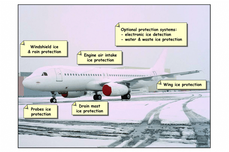
ICE AND RAIN PROTECTION SYSTEM COMPONENT LOCATION (2)
SYSTEM OVERVIEW
The ice and rain protection system enables unrestricted operation in icing conditions and heavy rain.
For anti-icing, hot air or electrical heating protects critical areas of the aircraft.
The different subsystems of the ice and rain protection system are:
– wing ice protection,
– engine air intake ice protection,
– probe ice protection,
– windshield ice and rain protection,
– drain mast ice protection,
– water and waste system ice protection (some are optional).
– visual lighted ice detection,
– electronic ice detection system (optional),
WING ANTI ICE PROTECTION
Hot air from the pneumatic system is provided for the anti-icing of the three outboard leading edge slats (3, 4 and 5) of each wing. Bleed air from the engines or the APU is supplied to each wing through a pressure regulating and shut off valve. Wing anti-ice supply to both wings is controlled by a single pushbutton switch on the overhead ANTI ICE panel.
ENGINE AIR INTAKE ANTI ICE PROTECTION
Each engine air intake is protected from ice by an independent air bleed supply from the high-pressure compressor of that engine. The air is supplied through the engine air intake anti-ice valve. Engine anti-ice is manually selected by the crew and is available in flight or on the ground with the engine running.
PROBE ICE PROTECTION
In order to provide reliable information for the air data systems, the air data probes are heated AUTOMATICALLY when at least one engine is running. Ice protection of the Angle Of Attack (AOA) sensors, pitot probes, static ports, and Total Air Temperature (TAT) probes is achieved by electrical heating. The PROBE/WINDOW HEAT pushbutton switch (normally in the AUTO position) may be used to select the probe heating ON with the engines shut down.
WINDSHIELD ANTI ICE PROTECTION
Electrical heating is provided for windshield anti-icing and cockpit side window de-fogging. The front windshields and side windows are heated AUTOMATICALLY when at least one engine is running. The PROBE/WINDOW HEAT pushbutton switch (normally in the AUTO position) may be used to select the window heating ON with the engines shut down.
DRAIN MAST ICE PROTECTION
When the electrical system is powered, the waste water Drain Masts are also electrically heated. The Drain Mast Heating is switched ON when the temperature is below a specific value. It is not always in operation. There are two Drain Masts located on the lower fuselage forward and aft sections. Two Control Units, located in the cargo compartments, control the Heating of the FWD and AFT Drain Masts.
系统概览
防冰和防雨系统可以确保在结冰和大雨情况下飞机不受限制的运行。
对于防冰,热气或电加热保护飞机的关键区域。
防冰和防雨的子系统功能如下:
-机翼防冰。
-发动机进气道防冰。
-探头防冰。
-挡风玻璃防冰和防雨。
-排水口防冰。
-净水和废水系统防冰(部分可选)。
-视觉照明冰面探测,
-电子冰面探测系统(可选),
机翼防冰
从气源来的热空气提供每个机翼的 3、4、5号外侧前缘缝翼的防冰,从发动机或 APU来的引气经过一个压力调节和关断活门输送至各机翼,两个机翼的防冰供气控制,仅需通过头顶防冰控制面板上的一个按钮开关即可实现。
发动机进气道防冰
发动机进气道防冰的热气来自独立的发动机高压压气机引气,供气通过发动机进气道防冰活门,在发动机运转的情况下,在地面或空中发动机防冰可以由机组人工接通。
探头防冰
为了提供大气系统稳定的数据,当一台发动机运转时大气系统探头自动加温,AOA传感器、全压管、静压孔和 TAT探头的防冰是电加温的,ROBE/WINDOW HEAT按钮(正常在自动位置)可以在发动机停车的情况下人工接通对探头进行加温。
风挡防冰
风挡防冰和除雾是电加温的,当一台发动机运转时前风挡和侧风挡的加温是自动的,PROBE/WINDOW HEAT按钮(正常在自动位置)可以在发动机停车的情况下人工接通对前和侧风挡进行加温。
排水口防冰
当接通电源时,废水排水桅杆就开始电加热了。灰水排水桅杆在温度低到一定的值后就开始加温,它并不总是工作,下机身前后共有两个排水桅杆桅杆,两个控制组件(位于货舱)控制前、后排水桅杆的加温。
![图片[1]-A320-30防冰防雨【系统原理】-航修札记](https://www.aeroacm.com/wp-content/uploads/2025/11/20251106002503871-word-image-10705-1.png)
ICE AND RAIN PROTECTION SYSTEM COMPONENT LOCATION (2)
COMPONENT LOCATION WING ICE PROTECTION
Two wing anti-ice control-valves are installed on the aircraft, one in each wing leading-edge outboard of the engine pylons.
机翼防冰组件位置
飞机上安装有两个机翼防冰控制活门,一个安装在发动机吊架的机翼前缘外侧。
![图片[2]-A320-30防冰防雨【系统原理】-航修札记](https://www.aeroacm.com/wp-content/uploads/2025/11/20251106002507518-word-image-10705-2.png)
ICE AND RAIN PROTECTION SYSTEM COMPONENT LOCATION (2)
ENGINE AIR INTAKE ICE PROTECTION
The engine anti-ice valve is installed on the lower right hand side of the engine.
发动机进气口防冰
发动机防冰活门安装在发动机右下方。
![图片[3]-A320-30防冰防雨【系统原理】-航修札记](https://www.aeroacm.com/wp-content/uploads/2025/11/20251106002541215-word-image-10705-3.png)
WING ICE PROTECTION
SYSTEM PRESENTATION (2)
SOURCES
The air for wing anti-icing is supplied by the pneumatic system.
VALVES
Hot air from the pneumatic system is supplied to each wing by an electrically controlled, pneumatically operated anti-ice control valve. The anti-ice control valves regulate the anti-icing pressure to approximately 23 psi. The valves also include high and low pressure switches to monitor the regulation function of the valve. In case of electrical failure or lack of pneumatic supply pressure, the valve closes.
CONTROLS
The wing anti-ice control valves are controlled from the cockpit by the WING Anti-Ice P/B. On the ground for test functions, a time-delay relay limits the opening of the valve to 30 seconds when the pushbutton switch is selected ON.
DUCTS
Air reaches slat 3 through a telescopic duct. It is distributed to the outboard slats by piccolo ducts, interconnected by flexible connections. A restrictor located downstream from the control valve adjusts the airflow. It also limits the flow in case of rupture of a distribution duct.
USERS
Only the three outboard slats are protected by the hot anti-icing air. Due to the aerodynamic characteristics of the wing, slats 1 and 2 do not need to be protected.
PRESSURE SWITCH
The two pressure switches monitor the pressure downstream of the butterfly valve to sense a valve malfunction. If the pressure increases to 2.1 bar (30.5 psi) the related switch gives a “high pressure ” signal. If the pressure decreases to 1.0 bar (14.5 psi) the related switch gives a “low pressure” signal.
气源
机翼防冰的气源来自气源系统。
活门
从气源系统来的热空气经过电控气动的防冰活门供到每一侧的机翼前缘,防冰活门调节防冰热气压力到大约 23PSI,活门还包括高压和低压电门以监控活门的功能,电源故障或无引气时,活门关闭。
控制
机翼防冰控制活门由驾驶舱的WING Anti-Ice P/B控制,地面测试时,当防冰选择电门 ON位时延时继电器控制防冰活门打开 30秒。
管路
热气通过一个伸缩管送到 3号缝翼,然后通过分配管路送到机翼外侧,活门下游有一个流量限制器调节气流大小,同时在管路漏气时也限制空气的流量。
用户
只有机翼前缘的外侧 3个缝翼有防冰保护,基于机翼的空气动力特性,1号和 2号缝翼不需要防冰。
压力电门
两个压力电门监控活门下游的压力,如果压力上升到30.5PSI,相应的电门给出超压信号,如果压力低于 14.5PSI,相应的电门给出低压信号。
![图片[4]-A320-30防冰防雨【系统原理】-航修札记](https://www.aeroacm.com/wp-content/uploads/2025/11/20251106002545926-word-image-10705-4.png)
SYSTEM INTERFACES (3)
P/BSW
The Wing Anti-Ice (WAI) P/BSW lets the WAI system be activated either during flight operation or during ground test operation for a limited time. It also sends the P/BSW configuration to the System Data Acquisition Concentrators (SDACs) and to the Engine Interface Units (EIUs). The WAI P/BSW acquires a discrete signal from the fault relay for the illumination of the FAULT light, during either valves transit or in case of disagreement between valves position and system selection or in case of LP detection.
EIU
The EIUs acquire system selection for engine power increase according to the bleed demand.
LGCIU
The Landing Gear Control and Interface Units (LGCIUs) send a shock absorber extended signal to the control relay to enable the system to be controlled when the A/C is in flight configuration.
SDAC
The SDACs acquire discrete inputs to display the system status on the ECAM warning page, ECAM MEMO page and ECAM BLEED page.
ACSC
The Air Conditioning System Controller (ACSC) 1 and 2 are interfacing with signals from the wing ice protection system. The ACSC acquires discrete inputs, to monitor the system and manage the bleed air. It stores failure data of the WAI system.
按钮
机翼防冰按钮可以在飞行中接通机翼防冰或在地面测试时接通机翼防冰一段时间,同时该按钮也发送构型信息给 EIU(发动机接口单元)和 SDACs(系统数据采集集中器),当活门在运动过程中或活门位置与系统选择的控制不同或压力探测异常时该按钮会从故障继电器收到一个离散信号以点亮故障灯。
EIU
EIU根据引气需求选择增加发动机功率来满足系统需求。
LGCIU
起落架控制和接口单元(LGCIU)向控制继电器发送减震器伸出信号,以便在飞机处于飞行构型时控制系统。
SDAC
SDAC采集离散输入,以便在 ECAM警告页面、ECAM MEMO页面和ECAM BLEED页面上显示系统的工作状态。
ACSC
ACSC(空调系统控制器)1和 2与机翼防冰系统有信号接口,ACSC接收机翼防冰离散信号监控机翼防冰系统并管理引气系统,它存储机翼防冰的故障数据。
![图片[5]-A320-30防冰防雨【系统原理】-航修札记](https://www.aeroacm.com/wp-content/uploads/2025/11/20251106002551877-word-image-10705-5.png)
ENGINE AIR INTAKE ICE PROTECTION
SYSTEM PRESENTATION (2)
USERS
The engine air intake is protected by its related bleed air, which heats the inlet leading edge in icing conditions. The hot air is then discharged overboard.
SOURCE
Hot air for the engine anti-ice system is supplied by a dedicated HP Compressor (HPC) bleed:
– on the V2500, 7th stage,
– on the CFM-56, 5th stage,
– on the PW6000, 9th stage.
The nacelle installed on CFM56 TECH INSERTION:
The modified Nacelle Anti-Icing (NAI) supply duct with the restrictor is required because of the new HPC higher air pressure and temperature at the 5th stage customer bleed ports. It complies with the certification requirement in case of duct rupture or failure occurring in the area of the NAI bleed air supply.
VALVE
The engine anti-ice system supply is controlled by an electrically controlled, pneumatically operated anti-ice valve. The solenoid is energized to CLOSE the valve, so in case of loss of electrical power supply, the valve will go fully open provided the engine bleed air supply pressure is high enough. In the absence of air pressure, the valve is spring-loaded to the closed position.
NOTE:The anti-ice valve of the CFM-56 engine uses an external 9 th stage muscle supply to open the valve.
CONTROLS
For each engine, the anti-ice valve is controlled by a P/BSW located on the ANTI ICE section of the overhead panel. When the engine Anti-ice (A.ICE) valve is open, a signal is sent to the Air Conditioning System Controller (ACSC), which calculates the bleed air demand and sends the signal tothe Full Authority Digital Engine Control (FADEC) via the Engine Interface Unit (EIU). The additional bleed demand decreases the maximum N1 for the CFM56 and PW6000 and the maximum Engine Pressure Ratio (EPR) limit for the V2500 relative to the ambient conditions and the engine operating conditions.
ECAM PAGE
If at least one of the two engine air intake anti-ice protection systems is selected ON, a message appears in green on the upper ECAM MEMO display. The signal received by EIU is used to avoid an unwanted anti ice fault ECAM warning on ground, when the engine is not running.
用户
发动机进气道防冰由相应的引气来加热进气道前缘,热空气会排放到机外。
气源
热气来自于相应的 HP压气机引气:
-CFM-56,5级引气。
-V2500,7级引气。
-PW6000,9级引气。
采用了新技术的 CFM56发动机:
改装过的进气道防冰供气管加了一个限流器,因为 HPC5级引气的压力和温度都比较高,在NAI引气供给区域发生管道破裂或故障时,符合认证要求
活门
发动机防冰系统供气由一个电控气动防冰活门控制。电磁阀是通电关闭,所以一旦供电故障,只要有足够的引气压力,进气道防冰活门就会打开,没有引气时,活门靠弹簧力关闭。
注:CFM56发动机的防冰活门使用 9级引气作为活门做动的气源。
控制
每台发动机的防冰活门均由位于头顶仪表盘防冰模块上的P/BSW控制。当防冰活门开启时,系统会向空调系统控制器(ACSC)发送信号,该控制器通过发动机接口单元(EIU)计算引气需求量,并将数据传输至全功率数字发动机控制系统(FADEC)。额外引气需求量的增加会导致CFM56和PW6000发动机的最大N1值降低,同时V2500发动机的最大压比(EPR)限制也会根据环境条件和发动机运行状态相应调整。
ECAM页面
如果至少选中两个发动机进气防冰系统中的一个,则上部ECAM MEMO显示器上会出现一条绿色信息。EIU接收的信号用于避免在发动机不运转时,在地面时出现不必要的防冰故障ECAM警告。
![图片[6]-A320-30防冰防雨【系统原理】-航修札记](https://www.aeroacm.com/wp-content/uploads/2025/11/20251106002555928-word-image-10705-6.png)
SYSTEM INTERFACES (3)
P/BSW
The P/BSW sends a discrete signal to the solenoid to open or close the valve, this information is also sent to the System Data Acquisition Concentrators (SDAC). The “FAULT” light comes on either during valve transit or in case of disagreement between valve position and system selection.
SDAC
The SDAC acquire the P/BSW configuration and the “FAULT” condition information to display system status on the ECAM warning page and ECAM MEMO page.
ACSC
The Air Conditioning System Controller (ACSC) 1 is responsible for the bleed management when the engine Anti Ice (A.ICE) system is switched ON. ACSC acquires the “valve not closed” position information from the valve position switch for bleed air management.
P/BSW按钮
P/BSW发送离散信号给电磁阀去开或者关活门,该信号也送给SDAC,活门在运动中或者活门位置与控制不一致时故障灯会亮。
SDAC
SDAC接收P/BSW的构型并将系统的状态显示在 ECAM警告页面或 ECAM MEMO页面上。
ACSC
ACSC1当发动机防冰接通时管理引气系统,ACSC需要从活门位置开关来的活门未关信号来管理引气系统。
![图片[7]-A320-30防冰防雨【系统原理】-航修札记](https://www.aeroacm.com/wp-content/uploads/2025/11/20251106002559662-word-image-10705-7.png)
SYSTEM PRESENTATION (2)
FUNCTION
The static ports, Angle-Of-Attack (AOA), pitot and Total Air Temperature (TAT) probes are electrically heated to prevent ice formation. The CAPT, F/O and STBY systems are independent. Each one includes a Probe Heat Computer (PHC), which controls probe and static ports heating. As there are only 2 TAT probes, the first one on the CAPT and the second one on the F/O, PHC 3 is not linked to a TAT probe.
CONTROL
The probes and static ports heating come on automatically when at least one engine is running. It can also be manually activated by the PROBE/WINDOW HEAT P/B. On ground, pitot heating is reduced and TAT heating is cut off, the Landing Gear Control and Interface Units (LGCIUs) control both. The Probe Heating System is also switched ON automatically when the LCGIU sends a FLIGHT signal.
PHC
Heating monitoring and fault indication is given by the related PHC. A probe or a sensor heating failure is sent to the ECAM via an Air Data/Inertial Reference Unit (ADIRU) and the Flight Warning Computers (FWC). The PHC also transmits fault messages to the Centralized Fault Display Interface Unit (CFDIU).
CAUTION
Pulling the PHC or Engine Interface Unit (EIU) power supply C/Bs causes unwanted heating of the probes and static ports. The system is also switched ON when the C/B of the LGCIU 1 and 2 is pulled (Flight signal).
功能
静压孔、AOA、皮托管和TAT是电加热防冰的,机长、副驾驶和备用系统是独立加温的。每一个系统都包含一个 PHC(探头加热计算机),它控制探头和静压口的加热,由于只有两个 TAT,机长一个,副驾驶一个,PHC3不管 TAT的加温。
控制
当至少有一台发动机运转时,探头和静压孔加热系统会自动启动。该功能也可通过PROBE/WINDOW HEAT P/B手动激活。在地面状态下,皮托管加热会降低,而TAT加热则会被切断——这一过程由起落架控制与接口单元(LGCIU)共同掌控。当起落架控制与接口单元发送飞行信号时,探头加热系统也会自动开启。
PHC
加热监测和故障指示由相关的PHC给出。探头或传感器加热故障通过空气数据/惯性参考单元(ADIRU)和飞行警告计算机(FWC)发送到ECAM。PHC还向集中式故障显示接口单元(CFDIU)发送故障信息。
注意
拔出 EIU的供电跳开关会导致探头和静压孔的自动加温,LGCIU1和 2跳开关拔出(空中信号)系统也会自动加温。
拔出PHC或发动机接口单元(EIU)供电跳开关会导致探头和静压孔产生不必要的加温。当LGCIU 1和2的跳开关被拔出时,系统也会被打开自动加温(飞行信号)。
![图片[8]-A320-30防冰防雨【系统原理】-航修札记](https://www.aeroacm.com/wp-content/uploads/2025/11/20251106002602604-word-image-10705-8.png)
SYSTEM DESCRIPTION/OPERATION (3)
GENERAL
This typical probe heat schematic shows an A/C on ground, electrically supplied, with the system “off”. Remember that the standby probe heat system has no Total Air Temperature (TAT) heating.
ADIRU
In case of a probe-heating fault the PHC sends a discrete output to its respective Air Data/Inertial Reference Unit (ADIRU), which in turn transmits the failure to the Flight Warning Computers (FWC).
CFDIU
The Centralized Fault Display Interface Unit (CFDIU) is connected to the PHC for fault system transmission. The PHC is a type 2 system: ARINC 429 output and maintenance test discrete input.
ENGINE RELAYS
The Engine Interface Unit (EIU) energizes the oil low-pressure and ground relays, when the related engine is not running.
概述
这个典型的探头加热示意图显示飞机在地面,供电,加温系统“关闭”。请记住,备用探头加热系统没有总空气温度(TAT)加热。
ADIRU
在出现探头加热故障时,PHC将发送一个离散输出至其相应的空气数据/惯性参考单元(ADIRU),然后由ADIRU将该故障传输至飞行警告计算机(FWC)。
CFDIU
集中式故障显示接口单元(CFDIU)与PHC连接,用于向系统传输故障信息。PHC是2类系统:ARINC 429输出和维护测试离散输入。
发动机继电器
发动机接口单元(EIU)在相关发动机不运行时,为滑油低压继电器和地面继电器通电。
![图片[9]-A320-30防冰防雨【系统原理】-航修札记](https://www.aeroacm.com/wp-content/uploads/2025/11/20251106002617605-word-image-10705-9.png)
SYSTEM DESCRIPTION/OPERATION (3)
CONTROL
Probes and static ports heating come on automatically when at least one engine is running. It can also be activated by the PROBE/WINDOW HEAT P/B. On ground, pitot heating is reduced and TAT heating is cut off.
LGCIU
When one of the three control conditions is met, the flight condition enables heating of the TAT sensor and full wave heating of the pitot probe.
控制
当至少有一个发动机运转时,探头和静压孔加热自动启动。也可通过PROBE/WINDOW HEAT P/B来激活。在地面上,皮托管加热会降低(低温),TAT加热则被切断。
LGCIU
当满足三个控制条件中的一个时,飞行条件使TAT传感器加温和皮托管探头的全波加热。
![图片[10]-A320-30防冰防雨【系统原理】-航修札记](https://www.aeroacm.com/wp-content/uploads/2025/11/20251106002624512-word-image-10705-10.png)
SYSTEM DESCRIPTION/OPERATION (3)
POWER SUPPLY
The Probe Heat Computer (PHC) is supplied with 28 VDC. The static ports are supplied with 28 VDC; the Angle-Of-Attack (AOA) sensor, TAT sensor and pitot probe are supplied with 115 VAC.
CAUTION FOR PHC C/B OPENED
If you pull the PHC power supplied C/B, the related probes and static ports will be fully heated.
供电
PHC由 28VDC供电,静压孔由 28VDC供电,AOA、TAT和全压管由 115VAC供电。
拔出 PHC跳开关的注意事项
如果拔出 PHC的供电跳开关,相应的探头会加温。
![图片[11]-A320-30防冰防雨【系统原理】-航修札记](https://www.aeroacm.com/wp-content/uploads/2025/11/20251106002629687-word-image-10705-11.png)
SYSTEM DESCRIPTION/OPERATION (3)
POWER SUPPLY (continued)
CAUTION FOR EIU C/B OPENED
If you pull the EIU power supplied C/B, the related engine oil low-pressure and ground relays are de-energized, the AOA probes and static ports will be heated and as the aircraft is on ground, the Pitot probes receive low heating only and the TAT sensor heating is inhibited.
供电(续)
拔出 EIU跳开关的注意事项
如果拔出 EIU供电跳开关,相关的发动机滑油低压电门和地面继电器断电,AOA和静压孔会加温,TAT不加温,全压管会低加温。
![图片[12]-A320-30防冰防雨【系统原理】-航修札记](https://www.aeroacm.com/wp-content/uploads/2025/11/20251106002633510-word-image-10705-12.png)
SYSTEM DESCRIPTION/OPERATION (3)
POWER SUPPLY (continued)
CAUTION FOR LGCIU C/B OPENED
If you pull the LGCIU power supplied C/B, the related probes and static ports will be fully heated.
供电(续)
拔出 LGCIU跳开关的注意事项
如果拔出 LGCIU供电跳开关,相应的探头和静压孔会进入全加温状态。
![图片[13]-A320-30防冰防雨【系统原理】-航修札记](https://www.aeroacm.com/wp-content/uploads/2025/11/20251106002637656-word-image-10705-13.png)
SYSTEM PRESENTATION (2)
FUNCTION
Windshields and side windows are electrically heated to maintain clear visibility in icing or misting conditions. The system is made up of two independent systems. Each one includes one Window Heat Computer (WHC), one windshield and two windows, one fixed and one sliding.
CONTROL
Windshield and windows heating comes on automatically when at least one engine is running. It can also be manually activated by the PROBE/WINDOW HEAT P/B. The windshield heating operates at low power on the ground and high power in flight.
WHC
Temperature regulation, overheat protection and fault indication are given by each WHC. In case of a windshield or window heating fault, the WHC sends an output signal to the ECAM via the System Data Acquisition Concentrator (SDAC). The WHCs also transmit fault messages to the Centralized Fault Display Interface Unit (CFDIU).
CAUTION
CAUTION: Pulling the Engine Interface Unit (EIU) power supply C/Bs causes the unwanted heating of the windshield and the side windows. If you have to pull the Landing Gear Control and Interface Unit (LGCIU) power supply C/Bs or before you lift the aircraft on jacks you have to accomplish the Flight Configuration Precautions, this prevents unwanted heating of the windshield and side windows.
功能
挡风玻璃和侧窗采用电加热,以便在结冰或起雾的情况下保持清晰的视野。该系统由两个独立的系统组成。每个系统包括一个窗加热计算机(WHC)、一个挡风玻璃和两个窗户,一个固定式和一个滑动式。
控制
当至少有一个发动机运转时,挡风玻璃和侧窗加热器自动启动。也可通过PROBE/风挡加温按钮手动启动。挡风玻璃加热器在地面上以低功率运行,在飞行中以高功率运行。
WHC
温度调节、过热保护和故障指示由每个WHC提供。如果挡风玻璃或侧窗加温出现故障,WHC通过系统数据采集集中器(SDAC)向ECAM发送输出信号。WHC还向中央故障显示接口单元(CFDIU)发送故障信息。
注意
注意:拔出发动机接口单元(EIU)供电跳开关会导致挡风玻璃和侧窗产生不必要的热量。如果必须拔出起落架控制和接口单元(LGCIU)供电跳开关,或在使用千斤顶举升飞机前,必须执行飞行构型注意事项,这可以防止挡风玻璃和侧窗产生不必要的热量。
![图片[14]-A320-30防冰防雨【系统原理】-航修札记](https://www.aeroacm.com/wp-content/uploads/2025/11/20251106002642668-word-image-10705-14.png)
SYSTEM DESCRIPTION/OPERATION (3)
GENERAL
The window and windshield anti-icing and demisting system is designed to maintain clear visibility through the cockpit front and side windows in icing or misting conditions. Windshields are de-iced, sliding and fixed windows are demisted.
SYSTEM DESCRIPTION
The Window Heat Computer (WHC) is supplied with 28 VDC. The fixed and sliding side windows are supplied with 115 VAC and the windshield is supplied with 200 VAC (dual phase 115 V AC).
CONTROL
The heating is cut off, when the three ground signals are sent to the AND logic. The windshield and windows are heated either when one engine is running (AUTO) or when the PROBE/WINDOW HEAT P/B is set to ON.
COMPUTER
WHC 1 controls and monitors the left hand side of the system and WHC 2 controls and monitors the right hand side. The WHC identifies and memorizes the faulty component. It also incorporates protection against over voltage due to lightning strike or static electricity on the windows. The WHC supplies independent temperature regulation between 35 and 42°C (95 and 107.6°F). For safety: heating is cut off if temperature reaches +/-60°C (140 or -76°F).
USERS
Each window comprises a heating element and two single loop sensors; one of the two sensors is a spare. Each windshield has a heating element and three loop sensors; only one sensor can be connected at a time. If that sensor fails, the maintenance has to swap the connectors to the spare sensor! The third sensor is an option.
ENGINE RELAYS
Oil LOW PRESSure and GrouND ReLaYs are energized by the Engine Interface Unit (EIU), when the related engine is not running.
LGCIU
Landing Gear Control and Interface Units (LGCIUs) inputs are used for the two heating levels of the windshield. The power is reduced on ground. When flight configuration is detected, the windshield is fully heated by the dual phase current.
SDAC
The System Data Acquisition Concentrators (SDACs) receive two discrete inputs from each WHC, one for the windshield and one for both windows to tell the crew about a heating fault.
CFDIU
The Centralized Fault Display Interface Unit (CFDIU) is connected to the WHC for fault system transmission. The WHC is a type 2 system, with an ARINC 429 output and a maintenance test discrete input.
概述
窗户和风挡防结冰和防雾系统设计用来可以在结冰条件或有雾时保证好的能见度(通过驾驶舱前侧和侧面的窗户),风挡是防冰的,滑动和固定窗户是防雾的。
系统介绍
WHC由 28VDC供电,固定和滑动侧窗由 115VAC供电,前风挡由 200VAC供电(115VAC双相)。
控制
当三个地信号送到AND逻辑时加温断开,一台发动机运转时(自动模式)或者当探头/窗户加温按钮接通时,风挡与窗户开始加温。
计算机
WHC1控制和监控左侧系统,WHC2控制和监控右侧系统,WHC识别并存储故障的部件,计算机还提供由于雷电或静电导致的过压保护,WHC提供温度调节在 32到 42摄氏度之间。安全起见:当温度达到正负 60摄氏度时加温断开。
用户
每个窗户都包括一个加热部件和两个单环传感器,一个传感器作为备份,每个风挡包括一个加热部件,三个传感器,一次只能连接一个传感器。如果该传感器发生故障,维修人员必须更换备用传感器的连接器!第三个传感器是可选的。
发动机继电器
当相关的发动机不运转时,低滑油压力和地面继电器由 EIU供电。
LGCIU
起落架控制与接口单元(LGCIU)的输入信号用于控制挡风玻璃的两个加热档位。地面时功率降低。当检测到飞行状态时,挡风玻璃将通过双相电流实现全加热。
SDAC
SDAC接收从每个 WHC来的两个离散信号,其中一个用来警告风挡加温故障,另一个用来警告两个窗户加温故障。
CFDIU
CFDIU连接到 WHC用于故障数据传输,WHC是 2类系统,有ARINC429输出和维护测试离散输入。
![图片[15]-A320-30防冰防雨【系统原理】-航修札记](https://www.aeroacm.com/wp-content/uploads/2025/11/20251106002645312-word-image-10705-15.png)
SYSTEM DESCRIPTION/OPERATION (3)
SYSTEM OPERATION WHEN AIRCRAFT ON GROUND, ENGINES RUNNING
When the A/C is on ground, engines running, the LGCIUs send “ground” signal to WHC, which sends “low level heating” for the windshield.
飞机在地面,发动机运转时系统的工作
飞机在地面,发动机运转,LGCIU发送ground信号给 WHC,WHC发送low level heating加温给风挡。
![图片[16]-A320-30防冰防雨【系统原理】-航修札记](https://www.aeroacm.com/wp-content/uploads/2025/11/20251106002650325-word-image-10705-16.png)
SYSTEM DESCRIPTION/OPERATION (3)
MAINTENANCE
CAUTION: If you have to pull the EIU power supply C/Bs, the related engine OIL LOW PRESS and GND RLYs are de-energized, this will cause windshield and windows to be heated.
维护
注意:如果要拔出 EIU的供电跳开关,相应的滑油压力低和地面继电器就会断电,这会导致风挡和侧窗自动加温。
![图片[17]-A320-30防冰防雨【系统原理】-航修札记](https://www.aeroacm.com/wp-content/uploads/2025/11/20251106002654324-word-image-10705-17.png)
RAIN REPELLENT SYSTEM PRESENTATION (2)
防雨系统概述(2)
FUNCTION
In heavy rain conditions, a rain repellent liquid, stored in a pressurized bottle, may be sprayed on the windshield to improve visibility. The spray nozzles are permanently purged by air from cabin hot air supply.
CONTROL
When the RAIN Repellent (RPLNT) P/B is pressed in, the solenoid valve opens for a short time. This causes a measured quantity of rain repellent liquid to be sprayed on to the related windshield. To repeat the cycle, the P/B must be pressed again. On ground, the rain repellent system is inhibited when both engines are shut down.
CAUTION
Make sure that the fluid does not stay on the A/C structure. If the fluid gets on the A/C structure, wash it off immediately with soap and water.
CAUTION: Do not apply the rain repellent fluid on a dry surface.
功能
在大雨条件下,储存在加压容器中的液态的防雨剂可以喷到风挡上提高能见度,喷嘴使用来自客舱的热空气来吹出残留的防雨剂。
控制
当防雨剂按钮按入时,电磁活门短时打开,使一定计量的防雨剂喷到风挡上,如果还要喷,则需要再次按入该按钮,地面上,双发关车后防雨剂的喷出受到抑制。
注意
确信防雨剂没有喷到飞机结构上,如果喷到了结构上,用肥皂水冲洗干净。
注意:不要把防雨剂喷到干的表面。
![图片[18]-A320-30防冰防雨【系统原理】-航修札记](https://www.aeroacm.com/wp-content/uploads/2025/11/20251106002657564-word-image-10705-18.png)
RAIN REPELLENT SYSTEM PRESENTATION (2)
DEACTIVATION
The system is still installed but can be optionally deactivated. For this the rain repellent bottle has been removed and C/B pulled, safetied and tagged. Clear visibility through the windshield is only achieved through the use of the wiper system.
失效
系统安装了,但可以选择性的使失效,为了达到这个目的可以拆下防雨剂容器,拔出相应跳开关并装好卡子,风挡在雨中只有使用雨刷来提高能见度。
![图片[19]-A320-30防冰防雨【系统原理】-航修札记](https://www.aeroacm.com/wp-content/uploads/2025/11/20251106002700486-word-image-10705-19.png)
RAIN REPELLENT SYSTEM D/O (3)
GENERAL
The system is designed to improve visibility through the windshield in heavy rain, particularly when the wipers are not sufficient. The system operates independently on the CAPT side and on the F/O side.
RAIN REPELLENT CIRCUIT
The rain repellent fluid used is packaged in a nitrogen-pressurized can. The can is directly attached to the rain repellent fluid gauge. A purge P/B is used when the can is replaced. A nozzle sprays the rain repellent fluid onto the related windshield through four orifices. The spray nozzles are symmetrical but not interchangeable:
– the CAPT spray nozzle is identified with red paint mark,
– the F/O spray nozzle is identified with yellow paint mark.
PURGE CIRCUIT
The spray nozzle lines are permanently purged by air from cabin hot air supply. The blow-out reservoir works as a pressure accumulator, a decanting reservoir and has a test connection.
OPERATION
Upon actuation of the P/B, the time-controlled solenoid valve of the associated side releases out fluid to the spray nozzle for a preset period of time. To initiate a new cycle, it is necessary to release, then to press the P/B again. Between each cycle, the lines are automatically and permanently purged by hot air. The pressure indication shows the nitrogen pressure in the bottle. When the needle is in the yellow range, or the can is completely empty, the bottle should be replaced.
概述
大雨中该系统可提高风挡的能见度,尤其在雨刷工作不力时,系统在机长侧和副驾驶侧工作是独立的。
防雨管路路
所使用的防雨液装在氮气加压罐中。该罐直接连接至防雨液液位计。更换罐体时需使用冲洗P/B。喷嘴通过四个孔口将防雨液喷洒至对应挡风玻璃。喷嘴呈对称布局但不可互换:
– 机长侧喷嘴以红色油漆标记,
– 副驾驶侧喷嘴以黄色油漆标记。
冲洗管路
喷嘴管路靠来自客舱的热气来持续冲洗,冲洗容器兼具压力蓄能器、沉淀储液罐功能,并配备测试接口。。
工作
按下P/B按钮后,对应侧的时间控制电磁阀将向喷嘴释放液体,持续预设时间。若要重复喷射,需先松开按钮,再重新按下P/B。每次循环间隙,来自(客舱的)热空气会冲洗管路。压力表显示瓶内氮气压力,当指针处于黄色区域或罐体完全排空时,应更换气瓶。
![图片[20]-A320-30防冰防雨【系统原理】-航修札记](https://www.aeroacm.com/wp-content/uploads/2025/11/20251106002704287-word-image-10705-20.png)
SYSTEM PRESENTATION (2)
GENERAL
The wastewater from the galley and lavatory compartment washbasins is dumped overboard through drain masts.
CONTROL SUPPLY
To protect drain masts against ice formation, electrical heating, through an automatically controlled system, is supplied when the A/C is electrically supplied.
USERS
The flexible heater foil, bonded on the drain mast tube, is temperature regulated via a sensor and powered by the drain mast heating Control Unit (CU). The AC power supply line, within the drain mast, is installed with a thermal switch opening at 120°C (250°F). It will regulate the temperature in case of normal temperature control failure.
CONTROL UNIT
The CU regulates the temperature of the drain mast tube. The correct operation of the system is monitored by the BITE function of the CU. Each CU regulates the heating temperature of the associated drain mast tube between 6°C (43°F) and 10°C (50°F).
MONITORING
The system status is sent to the Cabin Intercommunication Data System (CIDS) for indication on the Flight Attendant Panel (FAP). The failure of the Heater (HTR) or CU is indicated on the FAP by a CIDS CAUTion light, and on the front face of the CU by HTR and CU lights. The drain mast data is stored in the Centralized Fault Display Interface Unit (CFDIU).
TEST
To perform a complete test of the drain mast system, two tests must be carried out, one from the MCDU, and the second one on each CU. If the test is satisfactory:
– on the MCDU, the message “TEST OK” is displayed,
– on the front face of the CU, the HTR and CU lights are ON as long as the associated TEST P/BSW is pressed in.
If we have a fault on that system, the information is indicated by a CAUT light on the FAP and can be seen on the SYSTEM INFO, on page: “DRAINMASTS FAIL>
– CHECK WASTE WATER OVERFLOW FWD (AFT)”.
概述
从厨房或厕所来的灰水通过排水口排到机外。
控制供电
为了排水口防冰,有交流电供电的系统控制的自动电加热。
用户
绕在排水口管上的柔性加热箔片由加热控制器供电并调节温度。交流供电连到排水口处的一个过热电门上,该电门在 120摄氏度开路,在正常温度调节失效时它控制温度。
控制器
控制器调节排水口的加热温度,系统由控制器的 BITE监控,每个控制器调节温度到 6到 10摄氏度之间。
监控
系统状态发送到 CIDS用于显示在 FAP上,加热器或控制器故障由 FAP上的一个警告灯指示出来,同时在控制器上也有加热器和控制器的灯。排水口的数据存储在 CFDIU中。
测试
要完成完整的测试,要做两个测试,一个从 MCDU上,一个从控制器上,如果测试通过:
-MCDU上显示测试良好信息。
-控制器前面板上,加热器灯和控制器灯当测试按钮按下时长亮。
如果系统有故障,FAP上有警告灯提示,在 FAP系统信息页上会看到:排水口故障。
-检查排水溢流前(后)。
![图片[21]-A320-30防冰防雨【系统原理】-航修札记](https://www.aeroacm.com/wp-content/uploads/2025/11/20251106002709160-word-image-10705-21.png)
SYSTEM PRESENTATION (2)
GENERAL
The potable and waste water lines in sections 13 and 14 are insulated and electrically heated to prevent ice formation in or around the water lines. The system comprises a control unit and heater assemblies associated to two sensors.
CONTROL SUPPLY
Each system operates as soon as the A/C is electrically supplied.
CONTROL UNIT
Each control unit regulates the temperature range of each group of heater assemblies via their respective sensor.
TEST
A manual test of the system is available via a P/B located on the control unit. On the front face of the control unit, two green “OK” LEDs come on if the test is satisfactory
概述
净水和废水管路在机身 13和 14段部分做了隔热处理并有电加温防止在管路内部或周围结冰,该系统由控制器和与两个传感器相连的加热器组件组成。
控制供电
当交流电供电时系统开始工作。
控制器
每个控制器通过相应的传感器控制各组加热器的温度范围。
测试
人工系统测试可以通过位于控制器上的一个按钮进行,如果测试通过控制器前面板上两个绿色的 OK灯亮。
![图片[22]-A320-30防冰防雨【系统原理】-航修札记](https://www.aeroacm.com/wp-content/uploads/2025/11/20251106002712555-word-image-10705-22.png)
AIR STOP VALVE CARGO DRAINAGE SYS D/O (OPTION) (3)
general
Two air stop drain valves are installed on the forward and aft cargo compartment drainage lines, upstream of the forward and middle drain masts. These valves are electrically heated to prevent ice formation.
control supply
The system operates as soon as the aircraft is electrically supplied. The power supply is 115 V AC. This system is an option, as well as the MID drain masts.
temperature regulation
A thermostat controls the heating and the heater has an overheat protection.
概述
两个空气止排活门安装在前后货仓的排水管上,在前和中排水口的上游,这些活门是电加温防冰的。
控制供电
飞机接通电源系统开始工作,供电是 115VAC,系统是可选的,MID排水口也是可选的。
温度调节
恒温器控制加热,加热器有超温保护。
![图片[23]-A320-30防冰防雨【系统原理】-航修札记](https://www.aeroacm.com/wp-content/uploads/2025/11/20251106002716882-word-image-10705-23.png)
POTABLE WATER SERVICE PNL ANTI-ICE SYS D/O (3)
general
The fill/drain nipple at the potable water service panel is electrically heated to prevent ice formation.
Note: On the A318/A319/A321 the overflow nipple at the potable water service panel is also electrically heated.
control supply
The system operates as soon as the aircraft is electrically supplied.
temperature regulation
A thermostat controls the heating and the heater has an overheat protection.
概述
净水勤务面板上的加水和排水口是电加温的,防止结冰。
注:在 A318/319/321飞机上,净水溢流口也是电加温的。
控制供电
飞机电源接通系统开始工作。
温度调节
恒温器控制加热,加热器有超温保护。
![图片[24]-A320-30防冰防雨【系统原理】-航修札记](https://www.aeroacm.com/wp-content/uploads/2025/11/20251106002719439-word-image-10705-24.png)
TOILET SERVICE PNL ANTI-ICE SYS D/O (OPTION) (3)
GENERAL
The Rinse nipple 21 DV, of the toilet service panel, is electrically heated up and controlled by the thermostat 22 DV, to prevent ice formation.
CONTROL SUPPLY
The system operates as soon as the A/C is electrically supplied.
CONTROL UNIT
A heating element is installed to the rinse nipple of the toilet service panel to give protection against ice formation. A temperature thermostat is installed adjacent to this element and permanently measures the nipple temperature. The temperature thermostat is connected to the heating element. When icing conditions occurs, the thermostat will turn on the element for heating.
概述
测所勤务面板上的冲洗口 21DV是电加温的,由一个恒温器22DV控制,防止结冰。
控制供电
飞机电源接通,系统工作。
控制器
厕所勤务面板上冲洗口上安装有加热元件防止结冰,恒温器安装在冲洗口附近监控冲洗口的温度,恒温器连接到加热元件上,当结冰时,恒温器会接通加热元件开始加温。
![图片[25]-A320-30防冰防雨【系统原理】-航修札记](https://www.aeroacm.com/wp-content/uploads/2025/11/20251106002723386-word-image-10705-25.png)
SYSTEM PRESENTATION (3)
结冰指示器描述(3)
GENERAL
A visual ice indicator is installed in the central retainer of the windshield. It can be illuminated to check for icing conditions at night or in dark conditions.
ICE INDICATOR
The ice indicator on has a titanium part with openings, a transparent cover and a Light Emitting Diode (LED).
CONTROL
The indicator light LED is supplied with 28 VDC and controlled by the ICE INDicator & STandBY COMPASS switch.
概述
目视结冰指示器安装在风挡的中央柱条上,夜间可以通过灯光照明检查结冰情况。
结冰指示器
结冰指示器包括有开口的钛合金部件,一个透明盖和一个发光二极管。
控制
发光二极管由 28VDC供电,由一个电门控制。
![图片[26]-A320-30防冰防雨【系统原理】-航修札记](https://www.aeroacm.com/wp-content/uploads/2025/11/20251106002725259-word-image-10705-26.png)
DUAL ADVISORY ICE DETECTION DESCRIPTION/OPERATION (3)
双提醒结冰探测描述/工作(3)
FUNCTION
The purpose of the dual advisory ice detection system is to supply:
– A better detection of icing conditions,
– Fuel saving by cutting off the hot air bleed for the anti-ice systems when the latter are no longer necessary.
The dual advisory ice detection system is made of two ice detectors installed on the aircraft skin and directly connected to the Flight Warning Computer (FWC) to send warning messages to the crew on the Engine/Warning Display (EWD).
DETECTION
Two levels of detection are given:
– “ICE DETECTED” corresponding to an elementary detection,
– “SEVERE ICE DETECTED” corresponding to 7 successive elementary detections.
The ice detection system is operating at electrical power-up. It sends warning messages when the aircraft is in flight, depending on the altitude and when Total Air Temperature (TAT) is below 8°C (46.4°F), even with one ice detector faulty.
FWC MESSAGES
The ice detectors generate three different discrete signals:
– “ICE DETECTED” signal when engine air intake anti-ice is necessary,
– “SEVERE ICE DETECTED” signal when wing anti-ice is necessary,
– “ICE DETECT FAULT” signal when the two ice detectors are faulty.
This displays class 1 warning messages on the EWD. These messages can be respectively inhibited by engine or wing anti-ice selection.
RESET
When wing anti-ice valves are controlled to open, two ground signals are sent to the ice detectors in order to reset the ice detection counter and cut off the “SEVERE” signal.
MONITORING
Each ice detector is installed with a BITE function for continuous monitoring. Each ice detector sends a “FAULT” signal to System Data Acquisition Concentrators (SDACs) 1 and 2 and to the Centralized Fault Display Interface Unit (CFDIU) in case of failure during either power-up, MCDU or in operation tests. A class 2 fault message is displayed on the MCDU ANTI-ICE ICE DETECTOR 1 or 2 system page in case of ice detector failure.
功能
双提醒结冰探测系统的目的是提供:
-结冰条件下良好的探测功能。
-当防冰系统不需要工作时它会关掉防冰系统的供气来节省燃油。
双提醒结冰探测系统包括两个安装在飞机蒙皮上的结冰探测器,它直接与 FWC相连在 EWD上向机组提供警告信息。
探测
可以提供两个级别的探测:
-“ICE DETECTED”对应于基本探测。
-“SEVERE ICE DETEDTED”对应于 7次连续的基本探测。
结冰探测系统接通电源即开始工作,飞机在空中时,基于飞机高度并且 TAT小于 8摄氏度时,即使一个探测器故障,该系统也会发送警告信息。
FWC信息
结冰探测器产生三个不同的离散信号:
-“ICE DETECTED”信号当发动机进气道防冰需要时。
-“SEVERE ICE DETEDTED”信号当机翼防冰需要时。
-“ICE DETEDT FAULT”信号当两个探测器故障时。
在 EWD上显示 CLASS 1警告信息,这些信息可被发动机或机翼防冰的接通来抑制。
复位
当机翼防冰活门控制打开时,两个地信号送到结冰探测器去复位结冰探测并取消“SEVERE”信号。
监控
每个结冰探测器都不停的接受监控,当通电或用 MCDU测试时若结冰探测器故障其会发送 FAULT信号给 SDAC1和 2和 CFDIU。
若系统故障 CLASS 2级故障信息显示在 MCDU ANTI-ICE DETECTOR1或 2系统页面上。
![图片[27]-A320-30防冰防雨【系统原理】-航修札记](https://www.aeroacm.com/wp-content/uploads/2025/11/20251106002728344-word-image-10705-27.png)
ICE AND RAIN PROTECTION SYSTEM LINE MAINTENANCE (2)
MEL/DEACTIVATION
WING ICE PROTECTION
In case of failure, the aircraft may be dispatched per Minimum Equipment List with the RH WING anti-ice valve deactivated in the OPEN position or either valve in the CLOSED position. If the valve is deactivated OPEN, the associated engine bleed switch must be selected OFF until after takeoff. A flight manual performance penalty
is applied (fuel consumption is increased by 1%). If the valve is deactivated CLOSED, the aircraft may not be flown into icing conditions.
Procedure:
– Install zero-locking tool on slat/flap lever to prevent movement,
– Depressurize bleed air system,
– Remove access panel on wing lower surface,
– Move the valve indicator to the required position and install the locking screw OR,
– Move the valve indicator to the required position and install the locking plate.
MEL/使失效
机翼防冰
故障时,根据 MEL右机翼防冰活门使失效在开位或任一个机翼防冰活门使失效在关位飞机可以放行,如果防冰活门使失效在开位置,相关的发动机引气电门要选择 OFF直到起飞后才可以选择 ON,飞行性能要考虑(增加油耗大约 1%),如果活门使失效在关位置,飞机飞行中避免进入结冰区。
程序:
-在襟翼/缝翼控制手柄上安装锁销防止其运动。
-气源系统断开。
-打开机翼下表面的接近盖板。
-移动防冰活门指示器到相应的位置并安装锁定螺钉。或者
-移动防冰活门指示器到相应的位置并安装锁定盘。
![图片[28]-A320-30防冰防雨【系统原理】-航修札记](https://www.aeroacm.com/wp-content/uploads/2025/11/20251106002731887-word-image-10705-28.png)
ICE AND RAIN PROTECTION SYSTEM LINE MAINTENANCE (2)
MEL/DEACTIVATION (continued)
ENGINE AIR INTAKE ICE PROTECTION
In case of failure, the aircraft may be dispatched per Minimum Equipment List with one ENGINE anti-ice valve deactivated in the OPEN or CLOSED position. If the valve is deactivated OPEN, a Flight Manual performance penalty must be applied. Based on temperature and altitude, the maximum weight, takeoff speeds and fuel consumption will be adjusted. If the valve is deactivated CLOSED, the aircraft may not be flown into icing conditions.
Procedure:
– Full Authority Digital Engine Control (FADEC) ground power OFF,
– open RH fan cowl,
– move the manual override to the required position.
Lock in place with the locking pin, for CFM and V2500 engines. For PW6000 engines, the air intake anti-ice valve is locked manually with the locking lever in the OPEN position or the CLOSED position.
MEL/使失效(续)
发动机进气道防冰
若发生故障,根据 MEL一台发动机进气道防冰活门使失效在开或关位置可以放行飞机,如果活门使失效在开位置,飞行性能要考虑,温度、高度、最大重量、起飞速度和燃油消耗要调整,如果活门使失效在关位置,飞机飞行中避免进入结冰区域。
程序:
-FADEC地面电源 OFF。
-打开右侧风扇整流罩。
-移动人工超控手柄到需要的位置。
CFM和V2500发动机的进气口防冰活门通过锁定销固定。PW6000发动机的进气口防冰活门则通过锁定杆手动锁定,锁定杆可置于开启或关闭位置。
![图片[29]-A320-30防冰防雨【系统原理】-航修札记](https://www.aeroacm.com/wp-content/uploads/2025/11/20251106002735568-word-image-10705-29.png)
ICE AND RAIN PROTECTION SYSTEM LINE MAINTENANCE (2)
MEL/DEACTIVATION (continued)
DRAIN MAST ICE PROTECTION
In case of a failure of a drain mast heater, the fault will be displayed on the Flight Attendant Panel (FAP) of the Cabin Intercommunication Data System (CIDS). The aircraft may be dispatched per Minimum Equipment List with the drain mast heater inoperative. The water supply to the LAVatory(ies) (LAV(s)) and galley which use the failed drain mast must be shut off. As a result, the LAV(s). will not be usable and must be secured closed and locked.
MEL/使失效(续)
排水口防冰
一个排水口加热器故障时,故障会显示在 CIDS的 FAP上,根据 MEL排水口加热器故障飞机可以放行,使用该排水口的厨房和厕所的供水应关断,同时,相关的厕所应锁闭不能使用。
![图片[30]-A320-30防冰防雨【系统原理】-航修札记](https://www.aeroacm.com/wp-content/uploads/2025/11/20251106002739369-word-image-10705-30.png)
ICE AND RAIN PROTECTION SYSTEM LINE MAINTENANCE (2)
MAINTENANCE TIPS
When the aircraft is parked, it is recommended to install protective covers on the air data probes (static ports, pitot probes, AOA probes, TAT probes). The protective covers help protect the probes from contamination. The covers should be marked with REMOVE BEFORE FLIGHT. Ground personnel must insure that the covers are removed before flight or before power is applied to the probes (engine start or ground test). The probe heat system operates automatically to power the air data probe heaters when at least one engine is running. It is also designed to operate automatically when the aircraft is in flight. During the troubleshooting and the on ground operations, observe the following precautions:
– if the Probe Heat Computer (PHC) power supply C/B is pulled, the PHC internal relay will relax and the related probes will be heated. Make sure to pull ALL of the associated probe heat C/B’s (Static supply (28VDC), AOA supply, Pitot supply & TAT supply (all 115 VAC)).
– if the Engine Interface Unit (EIU) power supply C/B is pulled, the PHC will sense an “engine running” condition and the probes will be heated. Make sure to pull ALL of the probe heat C/B’s (Static supply (28VDC), AOA supply, Pitot supply & TAT supply (all 115 VAC)).
– if the C/B of the LGCIU is pulled, it simulates FLIGHT situation. So the probe heating is also switched ON.
防冰和防雨系统航线维护(2)
维护要点
当飞机停放时,建议在大气数据探头(AOA探头、全压管、静压孔、TAT探头)上安装保护套,保护套上应标明:飞行前取下。地面人员应确保飞行前或发动机启动前或测试前将保护套取下。
当一台发动机运转时探头自动加热,飞机升空后探头也是自动加热,地面排故时,注意以下注意事项:
-如果 PHC(探头加热计算机)供电跳开关拔出了,PHC内部继电器会松开相关的探头会加热,确信所有相关的探头加热跳开关都拔出(静压孔供电 28VDC、AOA和全压管还有 TAT探头供电115VAC)。
-如果 EIU供电跳开关拔出,PHC会认为发动机在运转并且探头会加温,确信拔出 EIU供电跳开关时同时拔出所有相关的探头加温跳开关(静压孔供电 28VDC、AOA和全压管还有 TAT探头供电115VAC)。
-如果 LGCIU的跳开关拔出,会模拟空中状态,同样,探头加温也会自动打开。
![图片[31]-A320-30防冰防雨【系统原理】-航修札记](https://www.aeroacm.com/wp-content/uploads/2025/11/20251106002742702-word-image-10705-31.png)


暂无评论内容