I.Curvic Coupling Inspection
弧形联轴器检查
- NOTE: Nomenclature for curvic coupling is provided in Figure 320.
- 注:图 320 中提供了弧形联轴器的命名。
(1) Inspect components with curvic coupling halves.
检查带有弧形联轴器半体的部件。
- NOTE: The importance of thoroughly cleaning the curvic coupling teeth prior to inspection cannot be over emphasized. Ensure fluorescent penetrant check has been performed and the part has been visually checked for cracks. Clean per CLEANING Section, 203K.
- 注意:在检查前彻底清洁弧形联轴器齿的重要性怎么强调都不为过。确保已进行荧光渗透检查,并目视检查零件是否有裂纹。按照清洁章节 203K 进行清洁。
(a) Visually check (in a well lighted area) curvic coupling teeth for nicks or metal buildup.
在光线充足的地方目视检查弧形联轴器齿是否有缺口或金属堆积。
(b) Remove nicks or metal buildup using Arkansas polishing stone ((white) SECTION VII). Return part to Honeywell for check and possible rework if curvic coupling damage is more severe.
使用阿肯色州抛光石((白色)第七章节)去除缺口或金属堆积。如果曲柄联轴器损坏较严重,请将零件返回霍尼韦尔进行检查并可能进行返工。
- NOTE: Two separate sets of curvic coupling gages are recommended; one set for checking tooth bearing pattern, and the other set for checking curvic coupling runout requirements.
- 注意:建议使用两套独立的曲柄联轴器量具;一套用于检查齿轴承模式,另一套用于检查曲柄联轴器的跳动要求。
(c) Prior to checking face and radial runout, verify master control coupling setup is within limits. Refer to Figure 321.
在检查端面和径向跳动之前,请确认主控制联轴器的设置是否在限值范围内。参见图 321。
(d) Check radial and face runout of curvic couplings using appropriate curvic coupling gages specified in applicable manual and a curvic coupling checking machine (Gleason No. 19) (SECTION VII). Refer to Figure 322 for parts with single curvic coupling, and Figure 323 for parts with two curvic couplings. Refer to the applicable manual for inspection features and acceptance criteria.
使用适用手册中规定的相应弧形联轴器量规和弧形联轴器检查机(格里森 19 号)(第七章节)检查弧形联轴器的径向和端面跳动。参见图 322 了解单弧形联轴器零件,参见图 323 了解双弧形联轴器零件。有关检查特征和验收标准,请参阅适用手册。
- If results are not acceptable, take bearing pattern by completing Step (f).
- 如果结果不可接受,请完成步骤(f)检查轴承模式。
- If results are acceptable, bearing pattern check in Step (f) is not required.
- 如果结果可以接受,则无需进行步骤(f)中的轴承模式检查。
(e) Check tooth bearing pattern on curvic couplings.
检查曲柄联轴器上的齿形轴承模式。
- 1 Polish each curvic coupling tooth using soft rubber abrasive (Brightboy No. ST70AL0612) (SECTION VII).
- 使用软橡胶研磨剂(Brightboy No. ST70AL0612)(章节 VII)打磨每个曲柄联轴器齿。
- NOTE: Too heavy or unevenly applied coating of marking compound (Orange Gleason Fluid) (SECTION VII), or marking compound (Dykem Hi-Spot Blue, No. 107) (SECTION VII), may cause false tooth bearing pattern indication.
- 注意:标记剂(橙色格里森流体)(第七章节)或标记剂(Dykem Hi-Spot Blue,编号107)(第七章节)涂得太厚或涂得不均匀,可能会导致假齿形轴承图案指示。
- 2 Apply trace of marking compound (Orange Gleason Fluid) (SECTION VII) to teeth of curvic coupling.
- 在曲柄联轴器的齿上涂抹少量标记剂(橙色格里森流体)(第七章节)。
- 3 Apply trace of marking compound (Dykem Hi-Spot Blue, No. 107) (SECTION VII) to teeth of appropriate curvic coupling gage or gages, specified in applicable manual, using a one-inch diameter soft bristled brush.
- 使用直径为1英寸的软毛刷,在适用手册中规定的相应弧形联轴器量规的齿上涂抹少量标记剂(Dykem Hi-Spot Blue,编号107)(章节VII)。
- 4 Position appropriate curvic coupling gage or gages and curvic coupling in place on fixture specified in applicable manual, exercising care to provide proper concave and convex match of curvic coupling teeth.
- 将相应的弧形联轴器量规和弧形联轴器小心地放置在适用手册中规定的夹具上,确保弧形联轴器齿的凹面和凸面正确配合。
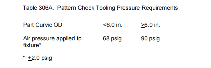
- 5 Apply regulated air pressure, as specified in applicable manual, to tooth pattern fixture to establish tooth bearing color transfer. If air pressure is not specified, use Table 306A.
- 按照适用手册的规定,对齿形夹具施加规定的空气压力,以确定齿轴承的色差。如果未规定空气压力,则使用表306A。

- NOTE: Pressure is applicable to Honeywell Fixture 289452-1 only.
- 注意:压力仅适用于霍尼韦尔夹具289452-1。
- CAUTION: MINOR NICKS, CONTAMINATION AND RAISED METAL WILL ADVERSELY AFFECT RUNOUT AND PATTERN INSPECTION. REFER TO STEP (c) FOR REMOVAL OF THESE CONDITIONS.
- 注意:轻微的缺口、污染和凸起的金属会对跳动和花纹检查产生不利影响。请参考步骤(c)以消除这些条件。
- NOTE: Some inspection requirements specify a “Partial” curvic pattern, which in technical terms is the same as a “localized” curvic pattern. When a Partial curvic pattern is specified, use the Localized Tooth Bearing Pattern Acceptance Specification requirements (Figure 325). On an attrition basis, the inspection procedures in the referencing manuals will be updated to use the term “localized” instead of “Partial”.
- 注意:一些检查要求规定了“局部”弯曲花纹,从技术角度来说,这与“局部”弯曲花纹相同。当规定局部弯曲花纹时,应使用局部齿形轴承花纹验收规范要求(图325)。根据磨损情况,参考手册中的检查程序将更新为使用“局部”一词代替“局部”。
- 6 Remove curvic coupling from tooth pattern tooling and check tooth bearing pattern for conformance to requirements specified in Figure 324 and Figure 325.
- 从齿形工具上拆下曲线联轴器,检查齿形是否符合图324和图325中规定的要求。
- If tooth bearing pattern is not acceptable, check for contamination, minor nicks or raised material. Repeat Steps (c) and (e).
- 如果齿形无法接受,检查是否有污染、轻微划痕或凸起。重复步骤 (c) 和 (e)。
- If runout check is still unacceptable, refer to the applicable REPAIR section or replace the part.
- 如果跳动检查仍然无法接受,请参阅适用的维修章节或更换零件。
- WARNING: SOLVENT VAPORS ARE TOXIC AND FLAMMABLE. DO NOT INHALE VAPORS. OBSERVE FIRE PRECAUTIONS.
- 警告:溶剂蒸汽有毒且易燃。切勿吸入蒸汽。遵守防火规定。
- 7 Clean marking compound (Dykem Hi-Spot Blue, No. 107) (SECTION VII) and marking compound (Orange Gleason Fluid) (SECTION VII) from curvic coupling teeth and tooling using solvent (Federal Specification PD-680, Type I) (SECTION VII) and a suede brush.
- 使用溶剂(联邦规格 PD-680,类型 I)(章节 VII)和麂皮刷清除曲柄联轴器齿和工具上的标记化合物(Dykem Hi-Spot Blue,编号 107)(章节 VII)和标记化合物(橙色 Gleason 流体)(章节 VII)。
- 8 Place curvic coupling in appropriate container to protect from damage.
- 将曲柄联轴器放入适当的容器中,以免损坏。

NOTE:
注:
- Datum plane A is the surface of the rotating table which master coupling 1 is installed.
基准平面A是安装主联轴器1的旋转工作台的表面。
- Datum axis B is the axis of rotation of the table.
基准轴B是工作台的旋转轴。
- -A- (Primary Datum Feature A) is the register face on master control coupling 1.
-A-(主基准特征A)是主控制联轴器1上的基准面。
- -B- (Secondary Datum Feature B) is the curvic coupling on master control coupling 1.
-B-(次基准特征B)是主控制联轴器1上的曲柄联轴器。
- Master control coupling 2 is used to align the axis of the secondary datum feature B with datum axis B. The alignment is correct when master control coupling 2 is rotated to four approximately equally spaced locations and the radial runout of its register diameter is constant at all four locations.
主控制联轴器2用于将辅助基准特征B的轴与基准轴B对齐。当主控制联轴器2旋转到四个大致等距的位置时,其径向跳动在所有四个位置都保持恒定,则说明对齐正确。
- Required to verify master control coupling 1 setup.
需要验证主控制联轴器1的设置。

NOTE:
注:
- Applies to face and radial runout as specified in the applicable manual.
适用于适用手册中规定的端面和径向跳动。
- Find the location of face(s) dimensioned to the curvic coupling by subtracting the master control coupling stacking distance from the inspected height.
从检查高度中减去主控制联轴器堆叠距离,即可找到曲柄联轴器端面的位置。
- Inspect the face runout and radial runout with the part rotated to four approximately equally spaced locations.
将零件旋转到四个大致等距的位置,检查端面跳动和径向跳动。
Runout Check
(Inspection Specifications for Single Curvic Couplings)
Figure 322

NOTE:
注:
- Find the part stack dimension between coupling pitch planes by subtracting the sum of the two master control coupling stacking distances from the inspected height.
从检测高度中减去两个主控制联轴器堆叠距离的总和,即可得出联轴器节距平面之间的零件堆叠尺寸。
- Relationship of first curvic coupling to part feature datums.
第一个曲轴联轴器与零件特征基准的关系。
- Find the location of faces dimensioned to lower curvic coupling by subtracting the lower master control couplings stacking distance from the inspected height.
从检测高度中减去下主控制联轴器堆叠距离,即可得出下曲轴联轴器尺寸的零件表面位置。
- Find the coupling to coupling face runout.
找出联轴器与联轴器表面跳动。
- Find the coupling to coupling radial runout.
找出联轴器径向跳动。
- Inspect the face runout and radial runout with the part rotated to four approximately equally spaced locations.
将零件旋转到四个大致等距的位置,检查端面跳动和径向跳动。

NOTES:
注:
(1) Pronounced pitted areas covering over 50 percent of the tooth bearing pattern on more than two adjacent teeth or more than 30 percent of the total number of tooth bearing surfaces are not acceptable.
超过两个相邻齿的齿面有超过50%的明显凹坑,或超过齿面总面积的30%,则不合格。
(2) Tooth bearing pattern shall be visible on at least 90 percent of the total number of teeth.
至少90%的牙齿上应能看到齿形。
(3) Lack of tooth bearing pattern shall not occur on any two adjacent teeth.
任何相邻的两颗牙齿上均不应出现无齿形的情况。

NOTES:
注:
(1) Pronounced pitted areas covering over 50 percent of the tooth bearing pattern on more than two adjacent teeth or more than 30 percent of the total number of tooth bearing surfaces are not acceptable.
明显凹陷区域覆盖超过50%的齿形,且超过两颗相邻牙齿或超过齿形总面积的30%,则视为不合格。
(2) Tooth bearing pattern shall be visible on at least 90 percent of the total number of teeth.
至少90%的牙齿上应能看到牙承托模式。
(3) Lack of tooth bearing pattern shall not occur on any two adjacent teeth.
任何相邻的两颗牙齿上不应出现牙承托模式缺失的情况。
J.Abraded, Plasma Spray, or Metal Spray Surfaces Inspection Refer to applicable manual for unit in work.
磨损、等离子喷涂或金属喷涂表面检查请参阅适用的部件工作手册。


暂无评论内容