一、名称
REVERSE FLOW CHECK CONTROL VALVE(RFCC)
反流止回控制器
二、件号
107494-1~-4,S212N101-29N-45
三、章节号
36-11-83
四、适用机型
B757
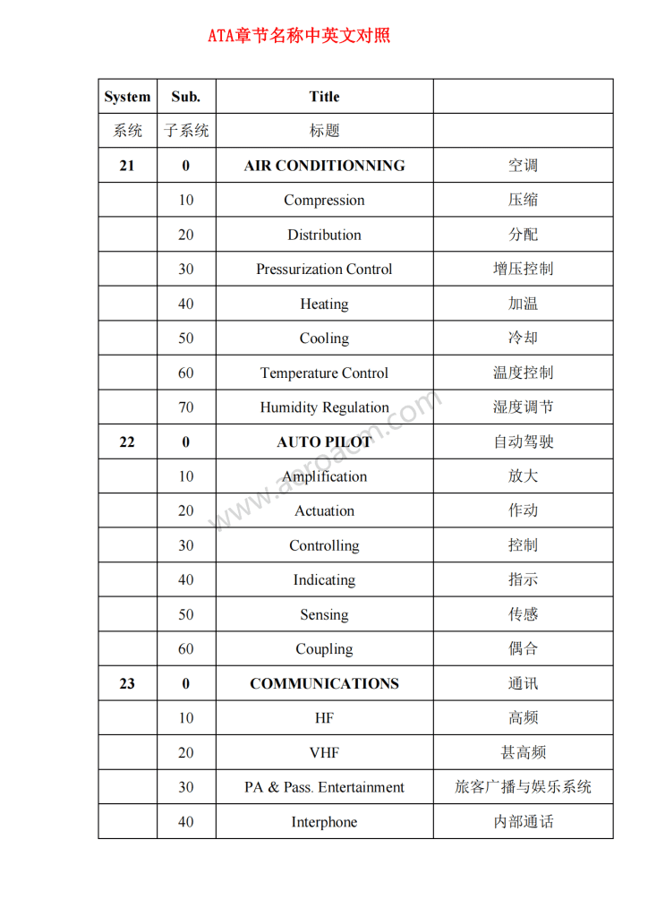
五、系统
21 AIR CONDITIONING
空调
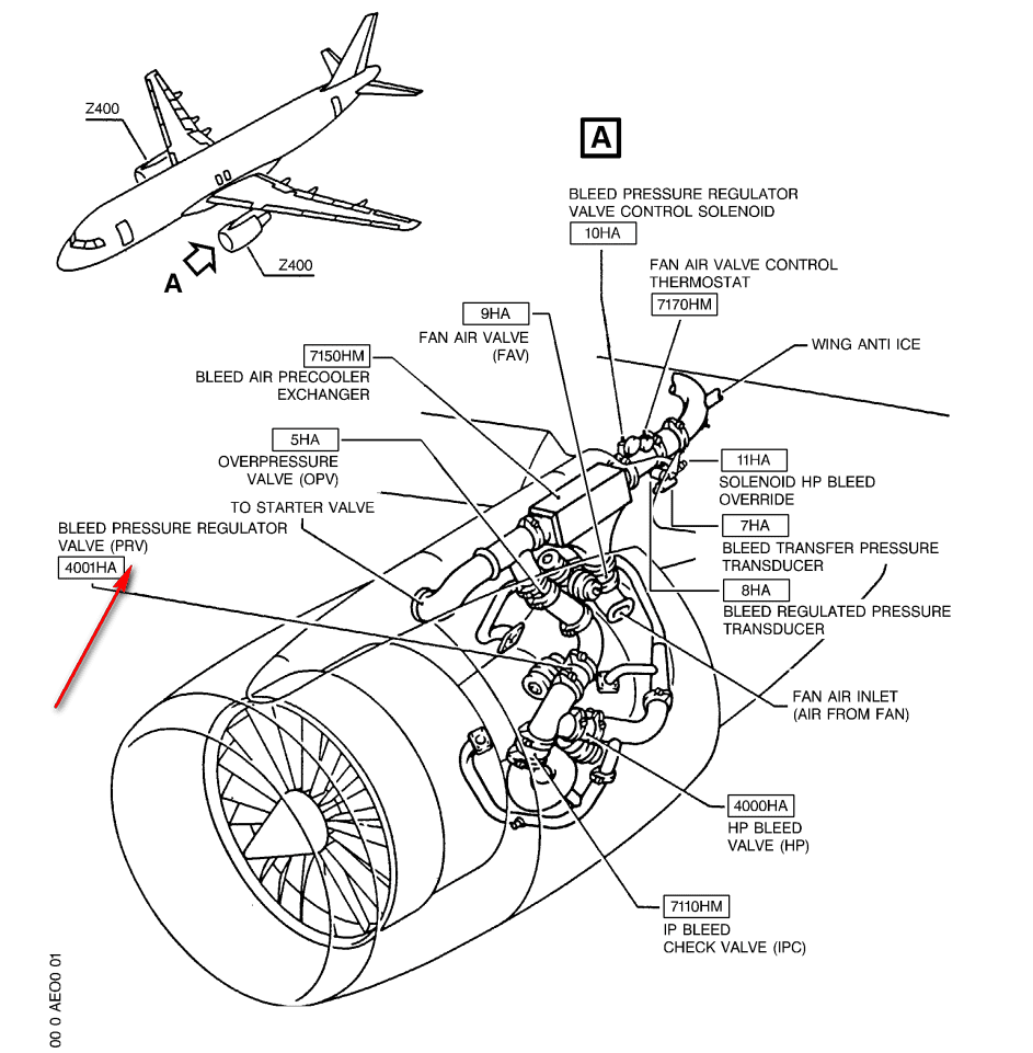
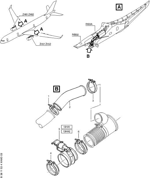
六、安装位置
发动机吊架
![图片[1]-107494 REVERSE FLOW CHECK CONTROL VALVE(RFCC)-航修札记](https://www.aeroacm.cn/wp-content/uploads/2025/08/word-image-8552-1.png)
![图片[2]-107494 REVERSE FLOW CHECK CONTROL VALVE(RFCC)-航修札记](https://www.aeroacm.cn/wp-content/uploads/2025/08/word-image-8552-2.png)
七、部件原理
General
概述
The reverse flow check control is a pneumatically actuated controller which compares two separate external pressures to actuate a normally closed sensitive switch. With zero pressure applied, a spring tends to push the switch toward a closed position. During normal operations, upstream pressure exceeds downstream pressure, which forces the switch to remain closed. In the event of a reverse flow condition, downstream pressure exceeds the upstream pressure and the switch is actuated to the open position. The open switch sends an electrical signal that results in closing the high stage valve and the pressure regulating and shutoff valve.
反流止回控制器是一种气动式控制器,通过比较两个独立的外部压力来驱动常闭式灵敏开关。当系统处于零压状态时,弹簧会将开关推至闭合位置。正常工作时,上游压力始终高于下游压力,使开关保持闭合状态。一旦出现逆流情况,下游压力超过上游压力,开关随即被触发至开启位置。此时,开路状态的开关会发送电信号,从而关闭高压级活门以及压力调节关断活门。
![图片[3]-107494 REVERSE FLOW CHECK CONTROL VALVE(RFCC)-航修札记](https://www.aeroacm.cn/wp-content/uploads/2025/08/word-image-8552-3.png)
![图片[4]-107494 REVERSE FLOW CHECK CONTROL VALVE(RFCC)-航修札记](https://www.aeroacm.cn/wp-content/uploads/2025/08/word-image-8552-4.png)
A. Reverse Flow Check Control Valve
反流止回控制器
(1) The reverse flow check control (controller) consists basically of a diaphragm cover assembly and a switch cover assembly.
反流止回控制器基本上由膜片盖组件和开关盖组件组成。
(2) The diaphragm cover assembly contains two spring loaded dual air diaphragms mounted between the switch cover assembly and diaphragm cover assembly. Also, the diaphragm cover assembly contains a differential pressure adjustment, cooling air outlet, upstream sense connection and downstream sense connection. The differential pressure adjustment determines the amount of spring load on the dual air diaphragms to adjust upstream and downstream sense port pressures.
膜片盖组件包含两个弹簧加载的双空气膜片,安装在开关盖组件与膜片盖组件之间。该组件还设有压差调节装置、冷却空气出口以及上游感应接口和下游感应接口。通过调节压差来控制双空气膜片的弹簧负载,从而精准调控上下游感应端口的压力值。
(3) The switch cover assembly contains a spring loaded L-shaped lever assembly mounted in a valve housing assembly and a sensitive switch assembly wired to an electrical connector. The lever assembly is held in contact with the sensitive switch assembly and the dual air diaphragms by a spring under one end of the lever assembly. Thus, any movement of the dual air diaphragms controls actuation of sensitive switch assembly. The sensitive switch assembly consists essentially of a micro switch and switch actuator. In addition, the switch cover assembly provides a mounting base for an identification and wiring diagram plate and a cooling air in connection.
开关盖组件包含一个安装在活门壳体内的弹簧加载L形杠杆组件,以及与电气连接器相连的灵敏开关组件。杠杆组件的一端通过弹簧与灵敏开关组件及双空气膜片保持接触,因此双空气膜片的任何位移都会触发灵敏开关组件的作动。该灵敏开关组件主要由微动开关和开关作行器构成。此外,开关盖组件还提供安装基座用于标识接线图板,并配备连接冷却空气系统。
NOTE: The schematic diaphragm depicted in Figure 3 shows the sensitive switch assembly in closed position and zero air pressure.
注:图3所示的膜片示意图显示了处于关闭位置和零气压下的灵敏开关组件。
(4) With zero air pressure applied to both Chambers A and B, the diaphragm spring force maintains the lever assembly in a position away from the switch actuator of the sensitive switch assembly.
由于腔室A和B均未施加气压,因此膜片弹簧力将杠杆组件保持在远离灵敏开关组件的开关致动器的位置。
(5) During normal operating conditions, Chamber A pressure is greater than that in Chamber B. The unbalanced pressure forces across the equal area diaphragm assembly prevent the lever assembly from activating the sensitive switch assembly. In the event that pressure in Chamber B exceeds pressure in Chamber A, the differential pressure acting across equal area diaphragm assembly overcomes the opposing spring force to actuate sensitive switch assembly.
在正常工作状态下,A室压力始终高于B室。这种压差作用力会持续作用于等面积膜片组件,从而阻止杠杆组件触发灵敏开关组件。当B室压力超过A室时,此时作用于膜片组件的压差将克服弹簧的反向作用力,从而激活灵敏开关组件。
![图片[5]-107494 REVERSE FLOW CHECK CONTROL VALVE(RFCC)-航修札记](https://www.aeroacm.cn/wp-content/uploads/2025/08/word-image-8552-5.png)
八、工作参数
![图片[6]-107494 REVERSE FLOW CHECK CONTROL VALVE(RFCC)-航修札记](https://www.aeroacm.cn/wp-content/uploads/2025/08/word-image-8552-6.png)
九、在飞机系统中的功能及其互联
![图片[7]-107494 REVERSE FLOW CHECK CONTROL VALVE(RFCC)-航修札记](https://www.aeroacm.cn/wp-content/uploads/2025/08/word-image-8552-7.png)
![图片[8]-107494 REVERSE FLOW CHECK CONTROL VALVE(RFCC)-航修札记](https://www.aeroacm.cn/wp-content/uploads/2025/08/word-image-8552-8.png)
The reverse flow controller is used to command the high stage valve pilot controller and PRSOV to OFF when downstream pressure from the PRSOV is higher than upstream pressure.
当来自PRSOV的下游压力高于上游压力时,反流控制器用于控制高压级活门先导控制器和PRSOV关闭。
简单来说就是,出现反流,给the high stage valve pilot controller指令和使PRSOV关闭
PNEUMATIC-GENERAL – DESCRIPTION/OPERATION
气动-概述-描述/操作
1 . General (Fig. 1)
概述
A. The pneumatic or air supply system supplies pressure and temperature regulated air to various systems. The supplied air is used as a working fluid, system power source or for system pressurization.
气动或空气供应系统为各种系统提供调节的压力和温度空气。所提供的空气用作工作流体介质、系统电源或用于系统加压。
B. The pneumatic system supplies air for these systems: aircraft pressurization, air conditioning , wing leading edge and engine cowl thermal anti-icing, engine starting, hydraulic reservoir pressurization,total air temperature (TAT) probe ambient air induction, rain repellent system pressurization and potable water tank pressurization.
气动系统为以下系统提供空气:飞机加压、空调、机翼前缘和发动机罩热防冰、发动机起动、液压油箱加压、总空气温度(TAT)探头环境空气进气、防水系统加压和饮用水箱加压。
C. The pnuematic system consists of the Air Supply Distribution System (AMM 36-10-00/001) and the Air Supply Indication System (AMM 36-20-00/001).
气动系统由供气分配系统(AMM 36-10-00/001)和供气指示系统(AMM 36-20-00/001)组成。
D. Air Supply Distribution System
供气分配系统
(1) Distribution Ducting
分配管道
(a) The pneumatic or air supply system is primarily an air distribution system, channeling air through ducts from one of several air sources to user systems. Pneumatic air is channeled through ducts to the hydraulic reservoir and potable water system, the total air temperature (TAT) probe, the air conditioning packs, wing thermal anti-ice ducts, and engine starter.
气动或空气供给系统主要是一个空气分配系统,通过管道将空气从多个空气源之一输送到用户系统。气动空气通过管道输送到液压油箱和饮用水系统、总空气温度(TAT)探头、空调包、机翼防冰导管和发动机起动机。
(2) Engine Air Supply
发动机空气供给
(a) The airplane engines provide the main source of pneumatic air. This air source is normally used whenever the engines are running. Air is supplied from two ports located at the engine compressor section. Through these ports a small amount of high pressure air is bled from the engines. The pneumatic system regulates the pressure and temperature of the air and channels it to the user systems.
飞机发动机是气动系统的主要气源。当发动机运转时,该气源通常持续供气。压缩机部分的两个接口负责输送空气,通过这些接口会从发动机中排出少量高压空气。气动系统会对空气压力和温度进行调节,并将空气输送至用户。
(3) APU Air Supply
APU供气
(a) The auxiliary power unit (APU) can be used to provide system air when the airplane is on the ground. The APU also provides inflight bleed air backup in case of engine failure or an engine pneumatic air system malfunction.
辅助动力装置(APU)可用于在飞机停放在地面上时提供系统空气。APU还提供飞行中引气备份,以备发动机故障或发动机气动系统发生故障时使用。
(4) Ground Air Supply
地面供气
(a) As an alternate to the APU, a pneumatic ground cart can supply air to the airplane whenever it is parked. Connection between the ground cart and the pneumatic system is through three ground air connectors.
作为APU的替代品,气动地面车可以在飞机停放时为其提供空气。地面车与气动系统之间的连接通过三个地面空气接头实现。
E. Air Supply Indicating System
供气指示系统
(1) Air Supply Pressure Indication
供气压力指示
(a) Pneumatic system duct pressure is read by duct pressure transducers located on the body crossover duct. The pressure is displayed by the Engine Indicating and Crew Alerting System (EICAS) (Ref 31-41-00) and on a dual duct pressure indicator (Ref 36-20-00).
气动系统管道压力由位于机体交叉管道上的管道压力传感器读取。压力通过发动机指示和机组警报系统(EICAS)(参考31-41-00)和双管道压力指示器(参考36-20-00)显示。
(2) Air Supply Temperature Indication
空气供给温度指示
(a) Bleed air temperature is sensed by the precooler out temperature bulb (Ref 36-20-00) and displayed by the Engine Indicating and Crew Alerting System (EICAS) (Ref 31-41-00).
预冷器外温度球(参考编号36-20-00)可感知空气温度,并通过发动机指示和机组警报系统(EICAS,参考31-41-00)显示。
![图片[9]-107494 REVERSE FLOW CHECK CONTROL VALVE(RFCC)-航修札记](https://www.aeroacm.cn/wp-content/uploads/2025/08/word-image-8552-9.png)
![图片[10]-107494 REVERSE FLOW CHECK CONTROL VALVE(RFCC)-航修札记](https://www.aeroacm.cn/wp-content/uploads/2025/08/word-image-8552-10.png)
DISTRIBUTION – DESCRIPTION AND OPERATION
分配-描述和操作
1 . General (Fig. 1)
概述
A. The air supply distribution system regulates the temperature and pressure of supply air extracted from the engines. It also transports supply air from the pneumatic sources (engines, auxiliary power unit (APU), and ground air connectors) to the user systems within the airplane.
空气供给分配系统调节从发动机中获得的供给空气的温度和压力。它还将供给空气从气动源(发动机、辅助动力装置(APU)和地面空气连接器)输送到飞机内的用户系统。
B. Pneumatic Air Sources
气动气源
(1) The primary source of air for the pneumatic system is engine bleed air. Bleed air is extracted from the left and right engines at intermediate and high pressure ports.
气动系统的主要空气来源是发动机引气。引气是从左右发动机的中压和高压端口获得的。
(2) Two secondary sources are the auxiliary power unit (APU) and three ground air carts. The APU is used with the airplane on the ground and as a backup system in flight. The ground air supply carts connect with three ground air connectors to supply compressed air to the airplane. The ground connectors are located on the wing to body fairing (two on the left side, one on the right side).
辅助动力装置(APU)和三台地面供气车是两个主要的辅助设备(次要来源)。APU在飞机在地面时作为辅助系统使用,飞行中则作为备用系统。地面气源车通过三个地面接口向飞机输送压缩空气,这些接口分布在机翼与机身整流罩之间(左侧两个,右侧一个)。
C. Pneumatic Air Requirements
气动空气要求
(1) The pneumatic system supplies air for aircraft pressurization, air conditioning, wing leading edge and engine cowl thermal anti-icing, engine starting, hydraulic reservoir pressurization, total air temperature (TAT) probe ambient air induction, rain repellent system pressurization, and potable water tank pressurization.
气动系统为飞机加压、空调、机翼前缘和发动机罩热防冰、发动机起动、液压油箱加压、总空气温度(TAT)探头环境空气进气、防水系统加压以及饮用水水箱加压提供空气。
D. Air Supply Control
供气控制
(1) The Bleed Air Control Panel (control panel) on the pilot’s overhead P5 panel provides air supply system control and indication. The control panel contains indication lights, duct pressure indicator, and four switch/lights which control valve position.
飞行员头顶P5面板上的Bleed空气控制面板(控制面板)提供空气供给系统控制和指示。该控制面板包含指示灯、导管压力指示器以及四个用于控制活门位置的开关/指示灯。
(2) The HI STAGE light illuminates when a system overpressure occurs upstream of the PRSOV.
当PRSOV上游出现系统超压时,HI STAGE灯会点亮。
(3) The BLEED light illuminates when a system overheat occurs.
当系统过热时,BLEED指示灯点亮。
(4) The DUCT LEAK illuminates when one of the system duct leak sensors detect hot air indicating a duct leak.
当系统通风管道泄漏传感器之一检测到热空气,指示通风管道存在泄漏时,DUCT LEAK将点亮。
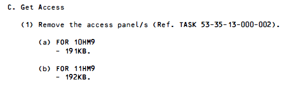
E . Engine Air Supply System (Fig. 2)
发动机空气供给系统(图2)
(1) Each engine air supply system consists of the following components: pneumatic ducting, intermediate pressure check valve, high pressure shutoff valve, high stage (HS) pilot, air supply precooler, reverse flow check controller, fan air modulating valve, fan air temperature sensor, air supply pressure regulating and shutoff valve and bleed air overtemperature sensor.
各发动机供气系统由以下部件组成:气动管道、中压单向活门、高压关断活门、高级(HS)pilot、供气预冷器、反流止回控制器、风扇空气调节活门、风扇空气温度传感器、供气压力调节和关断活门以及引气超温传感器。
(2) The engine air supply system controls the pressure, temperature and airflow of engine bleed air. Air is bled off the engine at the intermediate (HP2) pressure bleed port and high (HP6) pressure bleed port. At high engine power settings, HP2 bleed air flows through the intermediate check valve, the precooler, the pressure regulating and shutoff valve, and to system users. The high pressure shutoff valve remains closed during most high power settings. If the HP6 bleed air does not exceed the HP6 pressure limit schedule (101-113 psig up to 31,000 ft and 88-98 psig above 31,000 ft), the high pressure valve opens. The intermediate pressure check valve closes whenever downstream pressure exceeds upstream pressure preventing backflow into the intermediate (HP2) engine compressor section.
发动机供气系统负责调控发动机引气的气压、温度及气流状态。空气通过中间(HP2)压力引气口和高压(HP6)压力引气口排出。在高功率状态下,HP2引气会依次流经中压级单向活门、预冷器、调压和关断活门,最终进入系统用户端。高压关断活门通常保持关闭状态。当HP6引气未超过其压力限制曲线(海拔31,000英尺以下为101-113磅/平方英寸表压,海拔31,000英尺以上为88-98磅/平方英寸表压)时,高压活门便会开启。当中间压力超过上游压力时,中压级单向活门将自动关闭,有效防止气体逆流至HP2压缩机段。
(3) It is normal for the observed duct pressure (on the P5 panel) to decrease when the pneumatic pressure supply goes from the high stage port (HP6) to the low stage port (HP2). This could occur at different times for either the left or right sides. During this condition you can observe a split in duct pressure from the left to right side. This means that one side will have a higher duct pressure than the other side. You can see a graph of duct pressure versus EPR (engine power) in the “Low Duct Pressure” fault isolation procedure of the FIM 36-10-00/101. This graph gives the expected pressures for different engine power settings.
当气动压力从高压级端口(HP6)输送至低压级端口(HP2)时,P5面板显示的管道压力下降属于正常现象。这种情况可能出现在左右两侧的不同时间点。此时可观察到管道压力从左向右出现分压现象,即一侧压力高于另一侧。在FIM 36-10-00/101车型的“低管道压力”故障排查流程中,可以查看到管道压力与发动机功率(EPR)的关系曲线图。该图表展示了不同发动机功率设置下的预期压力值。
(4) Engine bleed air is ducted through the air supply precooler. The precooler is a crossflow, air to air, heat exchanger which uses engine fan air as its cooling medium. Fan air is routed to the precooler through the fan air modulating valve which is attached to the bottom of the precooler. The fan air modulating valve regulates the air flow to the precooler based on control air pressure from the fan air temperature sensor.
发动机引气空气通过供气预冷器进行导流。该预冷器采用横流式空气-空气热交换器结构,以发动机风扇空气作为冷却介质。风扇空气通过安装在预冷器底部的风扇空气调节阀输送至预冷器。该风扇调节活门根据来自风扇空气温度传感器的控制气压,精准调控进入预冷器的空气流量。
(5) Bleed air leaving the precooler is regulated by the pressure regulating and shutoff valve. The valve regulates bleed air between 40-53 psig. At engine settings when the bleed air pressure is below 40-53 psig, the valve is full open.
通过压力调节和关断活门来调节从预冷器排出的引气。该活门将引气调节在40-53 psig之间。在发动机设置中,当引气压力低于40-53 psig时,活门全开。
(6) A reverse flow check controller prevents pneumatic air from flowing back into the engine. When a backflow condition is sensed, the controller electrically actuates the closing solenoid of the pressure regulating and shutoff valve and the HS pilot.A small amount of fan air is bled from the fan air modulating valve to cool the reverse flow check controller and high stage pilot.
反流止回控制器可防止气动空气回流至发动机。当检测到逆流状态时,反流止回控制器会通过电控方式启动压力调节与关断活门的闭合电磁阀及高级(HS)pilot。此时系统会从风扇调压活门中分流少量气流,用于冷却反流止回控制器和高级(HS)pilot。
![图片[11]-107494 REVERSE FLOW CHECK CONTROL VALVE(RFCC)-航修札记](https://www.aeroacm.cn/wp-content/uploads/2025/08/word-image-8552-11.png)
![图片[12]-107494 REVERSE FLOW CHECK CONTROL VALVE(RFCC)-航修札记](https://www.aeroacm.cn/wp-content/uploads/2025/08/word-image-8552-12.png)
P . Reverse Flow Check Controller (Fig. 12)
反流止回控制器
(1) The controller is located in the strut forward of the precooler. The reverse flow check controller is a pneumatically actuated controller. The controller compares upstream and downstream duct pressure to actuate a normally closed sensitive switch. The controller is cooled by air routed from the fan air modulating valve.
控制器位于预冷器前支柱上。反流止回控制器是一个气动控制器。该控制器通过比较上游和下游管道压力来作动常闭式灵敏开关。控制器由来自风扇调节活门的空气进行冷却。
(2) The controller consists of a diaphragm assembly and a switch assembly.
控制器由膜片组件和开关组件组成
(a) The diaphragm assemby contains two spring loaded dual air diaphragms, a differential pressure adjustment screw, cooling air outlet, and upstream and downstream sense connections.
膜片组件包含两个弹簧加载的双空气膜片、一个压差调节螺钉、冷却空气出口以及上游和下游感应连接端。
(b) The switch assembly contains a spring loaded L-shaped lever assembly mounted in a valve housing and the sensitive switch wired to an electrical connector.
开关组件包含一个安装在阀壳体内的弹簧加载的L形杠杆组件,以及与电气连接器接线的灵敏开关。
(3) The lever is held in contact with the sensitive switch and the dual air diaphragms by a spring. Movement of the diaphragms caused by changes in sensed pressure controls actuation of the sensitive switch assembly. The sensitive switch assembly consists of a micro switch and a switch actuator.
杠杆通过弹簧与灵敏开关和双空气膜片保持接触。由感知压力变化引起的膜片移动控制灵敏开关组件的作动。灵敏开关组件由微动开关和开关作动器组成。
![图片[13]-107494 REVERSE FLOW CHECK CONTROL VALVE(RFCC)-航修札记](https://www.aeroacm.cn/wp-content/uploads/2025/08/word-image-8552-13.png)
A . Functional Description
功能说明
(1) Engine Pneumatic Control (Fig. 13)
发动机气动控制
(a) Pressing the L ENG Bleed switch/light on the pilot’s overhead P5 panel powers the left PRSOV/HP6 valve control relay if these conditions occur: 1) left engine fire switch is not armed 2) left engine start relay is not to start and 3) left reverse flow check controller signals forward flow.
按下驾驶舱顶部P5面板上的左发动机引气开关/指示灯,如果出现以下情况,将为左PRSOV/HP6活门控制继电器通电:1)左发动机防火开关未接通;2)左发动机起动继电器无法启动;3)反流止回控制器发出正向流量信号。
By powering the left PRSOV/HP6 valve control relay, power is removed from the left PRSOV/HP6 off relay and supplied to the left PRSOV/HP6 auto relay.
通过为左侧PRSOV/HP6活门控制继电器供电,将从左侧PRSOV/HP6关闭继电器中移除电源,并将电源供给左侧PRSOV/HP6自动继电器。
(b) When power is supplied to the left PRSOV/HP6 auto relay, a five second time delay is initiated. During this 5 second period, power is supplied to the opening coil of the HS pilot double-latching shutdown solenoid and to the auto coil of the pressure regulating and shutoff valve solenoid. This enables the HS pilot and the Pressure Regulating Shutoff Valve to the AUTO position. After the 5 second time delay, the PRSOV/HP6 auto relay opens to remove power from the opening coil of the HS pilot double-latching shutdown solenoid and from the auto coil of the pressure regulating and shutoff valve solenoid.
当向左侧PRSOV/HP6自动继电器通电时,系统会启动五秒延时保护机制。在此期间,HS pilot双锁止停机电磁阀的开口线圈与压力调节关断活门电磁阀的自锁线圈将获得供电,使HS pilot和压力调节关断活门进入自动工作模式。延时结束后,PRSOV/HP6自动继电器随即断开,切断对HS pilot双锁止停机电磁阀开口线圈及压力调节关断活门电磁阀自锁线圈的供电。
![图片[14]-107494 REVERSE FLOW CHECK CONTROL VALVE(RFCC)-航修札记](https://www.aeroacm.cn/wp-content/uploads/2025/08/word-image-8552-14.png)
![图片[15]-107494 REVERSE FLOW CHECK CONTROL VALVE(RFCC)-航修札记](https://www.aeroacm.cn/wp-content/uploads/2025/08/word-image-8552-15.png)
(c) If an overheat condition should exist at the air supply overheat switch, the left PRSOV/HP6 override relay is powered.The override relay removes power from the auto relay and powers the off relay. The high stage valve through the HS pilot closes and the PRSOV closes.
如果空气供应过热开关存在过热条件,则左侧PRSOV/HP6超越继电器通电。超控继电器切断自动继电器电源并为关闭继电器供电。通过HS pilot关闭高压级活门,同时PRSOV关闭。
(d) If the PRSOV is closed, the BLEED AIR OFF light comes on.
如果PRSOV关闭,BLEED AIR OFF灯就会亮起。
(e) If the airplane reaches 31,000 ft altitude, the air supply altitude switch closes, and powers the HS pilot switchover solenoid.
如果飞机达到31,000英尺高度,供气高度开关将关闭,并为HS pilot切换电磁阀供电。
(f) If an overpressure condition exists (greater than 125-135 psig) the HS pilot downstream overpressure sensor latches the high stage valve to close and provides a ground. The BLEED AIR HI STAGE light comes on and an EICAS advisory message L ENG HI STAGE appears.
如果存在超压条件(大于125-135 psig),HS pilot下游超压传感器将锁定高压级活门以关闭并提供接地。BLEED AIR HI stage指示灯点亮,且EICAS提示消息L ENG HI stage出现。
(g) When the PRSOV is closed, the closed position switch supplies a ground for the OFF light and for the EICAS advisory message L ENG BLEED OFF to be displayed.
当PRSOV关闭时,关闭位置开关为OFF指示灯和显示EICAS提示信息L ENG BLEED OFF提供接地。
(h) With greater air pressure in the upstream sense line of the reverse flow check controller, the diaphragm spring force in the controller keeps the lever assembly away from the switch. This allows the HS Pilot and PRSOV solenoids to stay in the auto position for normal operation.
在反流止回控制器的上游方向气压增大时,控制器中的膜片弹簧力使杠杆组件远离开关。这使得HS Pilot和PRSOV电磁阀保持在自动位置以进行正常操作。
(i) The fan air temperature sensor controls the operation of the fan air modulating valve. Should the valve become inoperative or malfunction, one of the following may occur:
风扇空气温度传感器控制风扇空气调节活门的操作。如果该活门发生故障或失灵,可能会出现以下情况之一:
1) Continuous periods of low pneumatic duct pressure,
气动管道压力持续低一段时间,
2) Low flight deck temperature,
低飞行温度
3) Air supply bleed air OFF light and BLEED light illuminated during flight.
飞行期间,空气供给系统引气关闭指示灯和bleed指示灯点亮。
(j) In the event downstream pressure exceeds upstream pressure (reverse flow condition) the differential pressure acting across the dual area diaphragms overcomes the opposing spring force to actuate the switch.
当下游压力超过上游压力(逆向流动状态)时,作用于双面积膜片的压差克服了相反的弹簧力以作动开关。
1) The actuation of the switch de-energizes the PRSOV/HP6 control relay. This sends a signal to the off solenoids of the pressure regulating and shutoff valve (PRSOV) and the HS pilot powering both closed.
开关的作动使PRSOV/HP6控制继电器断电。这会向压力调节阀(PRSOV)和HS pilot的关闭电磁阀发送信号,使二者都处于关闭状态。
2) Once upstream pressure exceeds downstream pressure the switch closes. Power is restored to the PRSOV/HP6 control relay, sending a signal to the auto solenoid of the PRSOV, restoring PRSOV operation to normal, and to the open solenoid of the high stage pilot.
一旦上游压力超过下游压力,开关就会闭合。电源将恢复到PRSOV/HP6控制继电器,向PRSOV的自动电磁阀发送信号,使PRSOV恢复正常操作,并向高压级pilot的打开电磁阀发送信号。
(k) Right engine control is similar to left engine control.
右发动机控制与左发动机控制类似。
![图片[16]-107494 REVERSE FLOW CHECK CONTROL VALVE(RFCC)-航修札记](https://www.aeroacm.cn/wp-content/uploads/2025/08/word-image-8552-16.png)
![图片[17]-107494 REVERSE FLOW CHECK CONTROL VALVE(RFCC)-航修札记](https://www.aeroacm.cn/wp-content/uploads/2025/08/word-image-8552-17.png)
![图片[18]-107494 REVERSE FLOW CHECK CONTROL VALVE(RFCC)-航修札记](https://www.aeroacm.cn/wp-content/uploads/2025/08/word-image-8552-18.png)
![图片[19]-107494 REVERSE FLOW CHECK CONTROL VALVE(RFCC)-航修札记](https://www.aeroacm.cn/wp-content/uploads/2025/08/word-image-8552-19.png)
![图片[20]-107494 REVERSE FLOW CHECK CONTROL VALVE(RFCC)-航修札记](https://www.aeroacm.cn/wp-content/uploads/2025/08/word-image-8552-20.png)
![图片[21]-107494 REVERSE FLOW CHECK CONTROL VALVE(RFCC)-航修札记](https://www.aeroacm.cn/wp-content/uploads/2025/08/word-image-8552-21.png)
![图片[22]-107494 REVERSE FLOW CHECK CONTROL VALVE(RFCC)-航修札记](https://www.aeroacm.cn/wp-content/uploads/2025/08/word-image-8552-22.png)
![图片[23]-107494 REVERSE FLOW CHECK CONTROL VALVE(RFCC)-航修札记](https://www.aeroacm.cn/wp-content/uploads/2025/08/word-image-8552-23.png)


暂无评论内容