机翼防冰活门38E93
一、名称
Wing Anti-Ice Control Valve
机翼防冰控制活门
二、件号
38E93-4 ,38E93-5 ,38E93-6
三、章节号
30-11-52
四、适用机型
A320
五、系统
30 ICE AND RAIN PROTECTION
防冰防雨
六、安装位置
大翼RIB 8和RIB 9之间
wing leading-edge outboard of the engine pylons
发动机吊架的机翼前缘外侧
![图片[1]-38E93 Wing Anti-Ice Control Valve【部件介绍】-航修札记](https://aeroacm.cn/wp-content/uploads/2025/02/word-image-2910-1.png)
![图片[2]-38E93 Wing Anti-Ice Control Valve【部件介绍】-航修札记](https://aeroacm.cn/wp-content/uploads/2025/02/word-image-2910-2.png)
七、部件原理
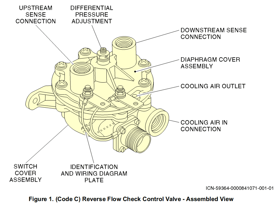
(1) The butterfly valve is normally closed due to spring load. An inlet pressure pickup for servo air is located about 0.5 inch (12.7 mm) upstream of the butterfly valve. Refer to Figure 2.
由于弹簧载荷,蝶板处于常闭状态。伺服空气的入口压力取压口位于蝶板上游约0.5英寸(12.7毫米)处。参见图2。
(2) When the solenoid valve is energized, the upper chamber is vented to atmosphere through a 0.031 inch (0.79 mm) diameter orifice in the solenoid valve. The pilot valve senses downstream pressure and modulates servo air into upper chamber. This pressure controls position of the actuator and butterfly valve. When downstream pressure changes, due to a change in inlet pressure, the pilot valve compensates by increasing or decreasing modulated pressure. This changes the position of the butterfly valve to maintain regulated pressure in duct.
当电磁阀通电时,上部腔室通过电磁阀中直径为0.031英寸(0.79 mm)的节流孔排放到大气中。先导阀感应下游压力并调节伺服空气进入上腔室。该压力控制作动器和蝶板的位置。当下游压力由于进口压力的变化而发生变化时,先导阀通过增加或减少调节压力进行补偿。这会改变蝶板的位置,以保持管道中的调节压力。
(3) When the valve is de-energized (closed), pressure in upper and middle chambers of valve assembly are equalized. The pressure differential across the small lower diaphragm, aided by spring pressure, causes the butterfly valve to close.
当活门断电(关闭)时,活门组件上部和中部腔室中的压力相等。下部小膜片上的压差在弹簧力的帮助下导致蝶板关闭。
![图片[3]-38E93 Wing Anti-Ice Control Valve【部件介绍】-航修札记](https://aeroacm.cn/wp-content/uploads/2025/02/word-image-2910-3.png)
八、工作参数
![图片[4]-38E93 Wing Anti-Ice Control Valve【部件介绍】-航修札记](https://aeroacm.cn/wp-content/uploads/2025/02/word-image-2910-4.png)
![图片[5]-38E93 Wing Anti-Ice Control Valve【部件介绍】-航修札记](https://aeroacm.cn/wp-content/uploads/2025/02/word-image-2910-5.png)
九、在飞机系统中的工作原理及互联
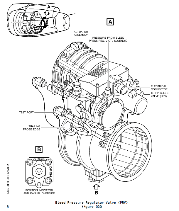
Two wing anti-ice control-valves are installed on the aircraft, one in each wing leading-edge outboard of the engine pylons. A single ON/OFF switch on the cockpit overhead panel (25VU) operates the two valves.
飞机上安装有两个机翼防冰控制活门, 每个发动机吊架机翼前缘外侧。通过在驾驶舱顶板(25VU)上的一个ON/OFF(接通/断开)电门来操控两个活门。
The wing anti-ice control-valve:
机翼防冰控制活门:
– isolates the anti-ice ducts from the pneumatic system bleed-air supply when anti-icing is not required
-当不需要防冰时, 隔绝防冰导管和气源系统引气
– controls the pressure of the wing anti-ice bleed-air, supplied by the pneumatic system.
-控制机翼防冰引气压力, 通过气压系统压力。
The valves are selected electrically and actuated pneumatically. If an electrical failure occurs, the valves will automatically go back to the closed position. The valves can be locked in the closed position to let the aircraft operate in non-icing conditions.
活门电气选择并气动操作。如发生电气故障, 活门将自动回到CLOSED位置。在非结冰情况下活门可锁在关闭位置让飞机运行。
NOTE : The RH anti-ice control valve can be locked in the OPEN position, but the correct ECAM procedure must be applied (REF. 30-11-00-04).
注: 右防冰控制活门可能锁在OPEN位置, 但必须应用正确ECAM程序(参见 30-11-00-04)。
When the valve(s) is/are locked in the CLOSED position, the aircraft is not permitted to fly into icing conditions. A microswitch in the anti-ice valve senses when the valve is closed and gives a CLOSED/NOT CLOSED signal to the Environmental Control System Zone Control and Bleed Status Computer (ECS computer) and the Electronic Centralized Aircraft Monitoring (ECAM) system.A visual/mechanical valve position indication is also given.
当活门锁定在关闭位置时, 不允许飞机在结冰气候条件下飞行。当防冰活门关闭,微动开关将触发作动,并给出一个CLOSED/NOT CLOSED信号到环境控制系统区控制器和引气状态计算机(ECS计算机)和飞机电子中央监控(ECAM)系统。也提供一个可视/机械活门位置指示。
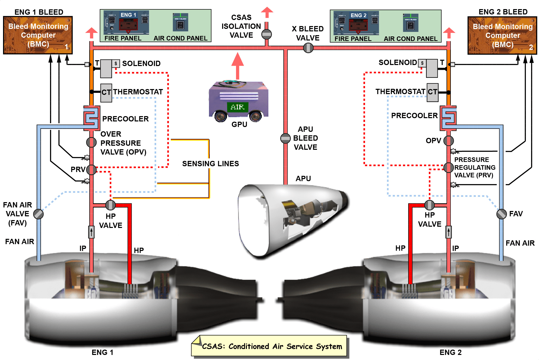
The wing ice protection system is supplied with hot air from the pneumatic system, downstream of the pre-cooler. The anti-ice control valve (in the wing, outboard of the engine pylon) isolates these two systems. A restrictor downstream of the anti-ice control valve controls the air flow.The hot air goes through a lagged duct that connects the anti-ice control valve to the telescopic duct, inboard of RIB 13. The telescopic duct only attaches to the piccolo ducts in the slat 3. The piccolo ducts 3, 4 and 5 (that connect together with flexible ducts) release the hot air to heat the slats. The piccolo ducts release the air into the slats through holes along their foward length. The air flows around the forward area of the slat then goes through acceleration slots into the rear section. It is then released overboard through the holes in the bottom surface of the slat.
气源系统的预冷却器下游为机翼防冰系统提供热空气。防冰控制活门(机翼,在发动机吊架外侧)隔离了这两个系统。一个防冰控制活门节气阀下游控制气流。热空气流过一个装有隔热套的管道,该管道将防冰控制活门和RIB 13处的内侧伸缩管连接起来。伸缩管道仅连接到3号缝翼小型导管。小型导管 3,4和 5(和柔性管道连接在一起)释放热空气以加热缝翼。小型导管沿着它的前段的孔释放空气进入缝翼。空气围绕缝翼前方的区域流动然后通过加速度槽进入后部。然后空气从缝翼底部表面的孔排出机外。
![图片[6]-38E93 Wing Anti-Ice Control Valve【部件介绍】-航修札记](https://aeroacm.cn/wp-content/uploads/2025/02/word-image-2910-6.png)
![图片[7]-38E93 Wing Anti-Ice Control Valve【部件介绍】-航修札记](https://aeroacm.cn/wp-content/uploads/2025/02/word-image-2910-7.png)
![图片[8]-38E93 Wing Anti-Ice Control Valve【部件介绍】-航修札记](https://aeroacm.cn/wp-content/uploads/2025/02/word-image-2910-8.png)
十、系统介绍/拓展知识
The wing ice protection system:
The wing ice protection system prevents ice on the leading edge of the slats 3, 4 and 5. The system, which is the same in the LH and the RH wing, uses hot air from the pneumatic system (Ref. 36-00-00). It is available in all flight conditions. The two engines usually supply the pneumatic system with bleed air. If there is a failure, the cross-bleed valve opens and one engine can supply the two wings.The system is only used during flight, but can be tested on the ground. To prevent heat damage to the slats, the ground test stops automatically after 30 seconds.
大翼防冰系统:
大翼防冰系统用来防止在3,4和 5号缝翼前缘出现结冰。该系统(在左侧和右侧大翼是相同的)使用来自气源系统(Ref. 36-00-00)的热空气。在所有飞行条件下它都是可用的。这两个发动机通常用引气供给气源系统。如果出现故障,交输引气活门打开并可由一台发动机给二个大翼供气。系统只在飞行过程中使用,但可在地面上进行测试。以防止缝翼受到过热损伤,地面测试在30秒后自动停止。
![图片[9]-38E93 Wing Anti-Ice Control Valve【部件介绍】-航修札记](https://aeroacm.cn/wp-content/uploads/2025/02/word-image-2910-9.png)


暂无评论内容