一、名称
FAN AIR TEMPERATURE SENSOR
风扇空气温度传感器
二、件号
773284-3~-7,S210T120-8,-38,-48
三、章节号
36-12-07
四、适用机型
B767
五、系统
36-PNEUMATIC
气动
六、安装位置
发动机吊架
![图片[1]-773284 FAN AIR TEMPERATURE SENSOR-航修札记](https://www.aeroacm.com/wp-content/uploads/2025/11/20251111222844797-word-image-10796-1.png)
七、部件原理
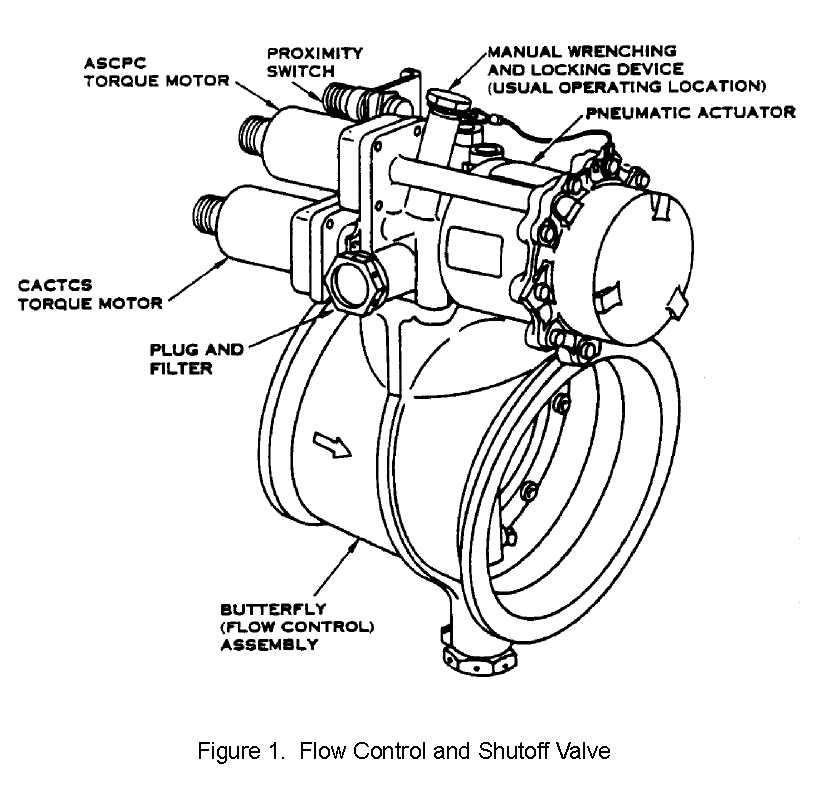
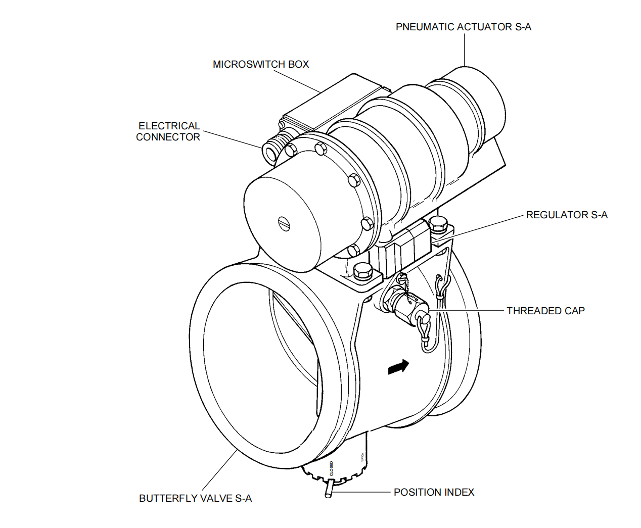
1. Description (See Figure 1, Figure 2, or Figure 3)
A. The fan air temperature sensor consists of a sensor body containing a lever and crank, a sensor diaphragm, compensating springs, a poppet and nozzle, a bimetallic temperature probe, ball poppet relief valve, two BITE pressure switches, and a BITE temperature sensor.
B. An inline filter is located in the bleed air servo line upstream of two internal flow restrictors and the ball poppet relief valve.
C. The fan air temperature sensor is installed in the bleed air duct between the air supply precooler and the cowl thermal anti-ice takeoff duct.
1. 描述(参见图1、图2或图3)
A. 风扇空气温度传感器由以下部件组成:含杠杆与曲柄的传感器主体、传感器膜片、补偿弹簧、球阀与喷嘴、双金属温度探头、球阀泄压阀、两个BITE压力开关及BITE温度传感器。
B. 管路式滤清器位于引气伺服管路中,其位置在两个内部流量限流孔及球阀泄压阀的上游。
C. 风扇空气温度传感器安装于引气管道中,位置介于空气供应预冷器与整流罩防冰系统起始管道之间。
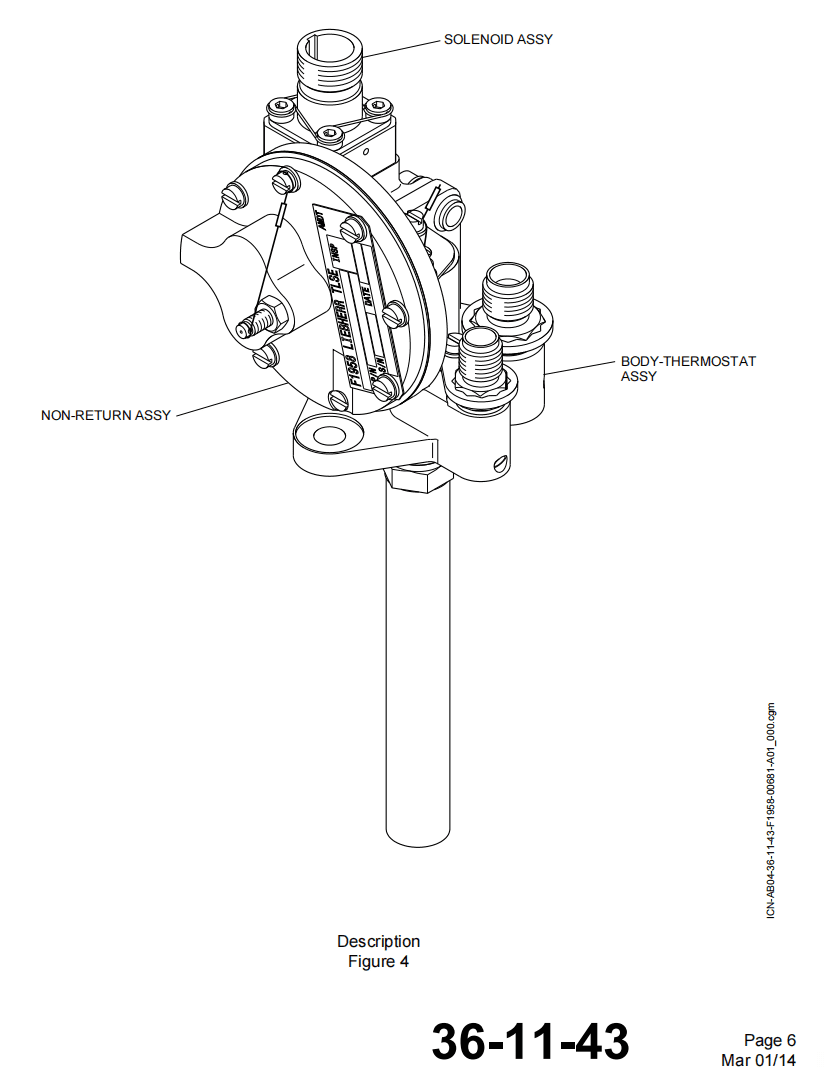
2. Operation (Refer to Figure 4 and Figure 5)
A. Signal pressure from the bleed air duct is regulated by a ball poppet regulator and controlled by a nozzle and poppet before acting in the fan air modulating valve as servo pressure.
B. The ball poppet regulator bleeds off excess pressure providing as essentially regulated supply to the sensor thereby reducing supply pressure variations and improving temperature sensor accuracy.
C. The bimetallic element in the bleed fan air temperature probe, reacting to temperature variations in the bleed air, produces a force change on the sensor lever through the sensor crank. The lever movement results in a proportional change in signal pressure acting on the sensor diaphragm to keep the lever in balance.
D. The adjusted signal pressure is sent to the fan air modulating valve controller and sets valve position thereby achieving a proportional temperature control.
E. BITE pressure switches react to signal pressure changes. The low pressure switch (PTL) actuates between 2.8 and 6.1 in. Hg. The high pressure switch (PTH) actuates between 16.3 and 21.4 in. Hg. Both switches provide signals to the BITE module.
F. A BITE temperature sensor senses temperature change and varies an electrical signal to the BITE module.
2. 工作原理(参见图4和图5)
A. 来自引气管路的气压信号经球阀调节器调节,通过喷嘴和阀芯控制后,作为伺服压力作用于风扇空气调节活门。
B. 球阀调节器释放过剩压力,为传感器提供基本稳定的供气,从而减少供气压力波动并提高温度传感器的精度。
C. 引气风扇空气温度探头内的双金属元件响应引气温度变化,通过传感器曲柄使传感器杠杆产生力变化。杠杆运动导致作用于传感器膜片的信号压力成比例变化,从而维持杠杆平衡。
D. 经调节的信号压力传送至风扇空气调节活门控制器,设定活门位置以实现比例温度控制。
E. BITE压力开关响应信号压力变化。低压开关(PTL)在2.8至6.1英寸汞柱范围内动作,高压开关(PTH)在16.3至21.4英寸汞柱范围内动作。两者均向BITE模块提供信号。
F. BITE温度传感器感知温度变化,并向BITE模块发送相应的电信号。
![图片[2]-773284 FAN AIR TEMPERATURE SENSOR-航修札记](https://www.aeroacm.com/wp-content/uploads/2025/11/20251111222845210-word-image-10796-2.png)
![图片[3]-773284 FAN AIR TEMPERATURE SENSOR-航修札记](https://www.aeroacm.com/wp-content/uploads/2025/11/20251111222846384-word-image-10796-3.png)
![图片[4]-773284 FAN AIR TEMPERATURE SENSOR-航修札记](https://www.aeroacm.com/wp-content/uploads/2025/11/20251111222847308-word-image-10796-4.png)
![图片[5]-773284 FAN AIR TEMPERATURE SENSOR-航修札记](https://www.aeroacm.com/wp-content/uploads/2025/11/20251111222848843-word-image-10796-5.png)
![图片[6]-773284 FAN AIR TEMPERATURE SENSOR-航修札记](https://www.aeroacm.com/wp-content/uploads/2025/11/20251111222850992-word-image-10796-6.png)
八、工作参数
N/A
九、在飞机系统中的工作原理及互联
简单来说:控制FAV
The fan air temperature sensor, found in the strut PRSOV compartment, looks at precooleroutput-air temperature. The sensor controls the fan-air-modulating valve which in turn controls the amount of cooling air to the precooler. The fan-air-temperature- sensor works to keep precooler-output temperature at 204℃±17℃ (400℉±30℉).
安装在支柱PRSOV舱内的风扇空气温度传感器,用于监测预冷器出口空气温度。该传感器通过控制风扇空气调节活门,进而调节供给预冷器的冷却空气流量。其工作原理是将预冷器出口温度维持在2048℃±178℃(4008℉±308℉)范围内。
AIR SUPPLY DISTRIBUTION SYSTEM – DESCRIPTION AND OPERATION(EFFECTIVITY BEJ 005, 006, 301-999)
空气供应分配系统 – 描述与操作(EFFECTIVITY BEJ 005, 006, 301-999)
1. General(Figure 1)
概述(图1)
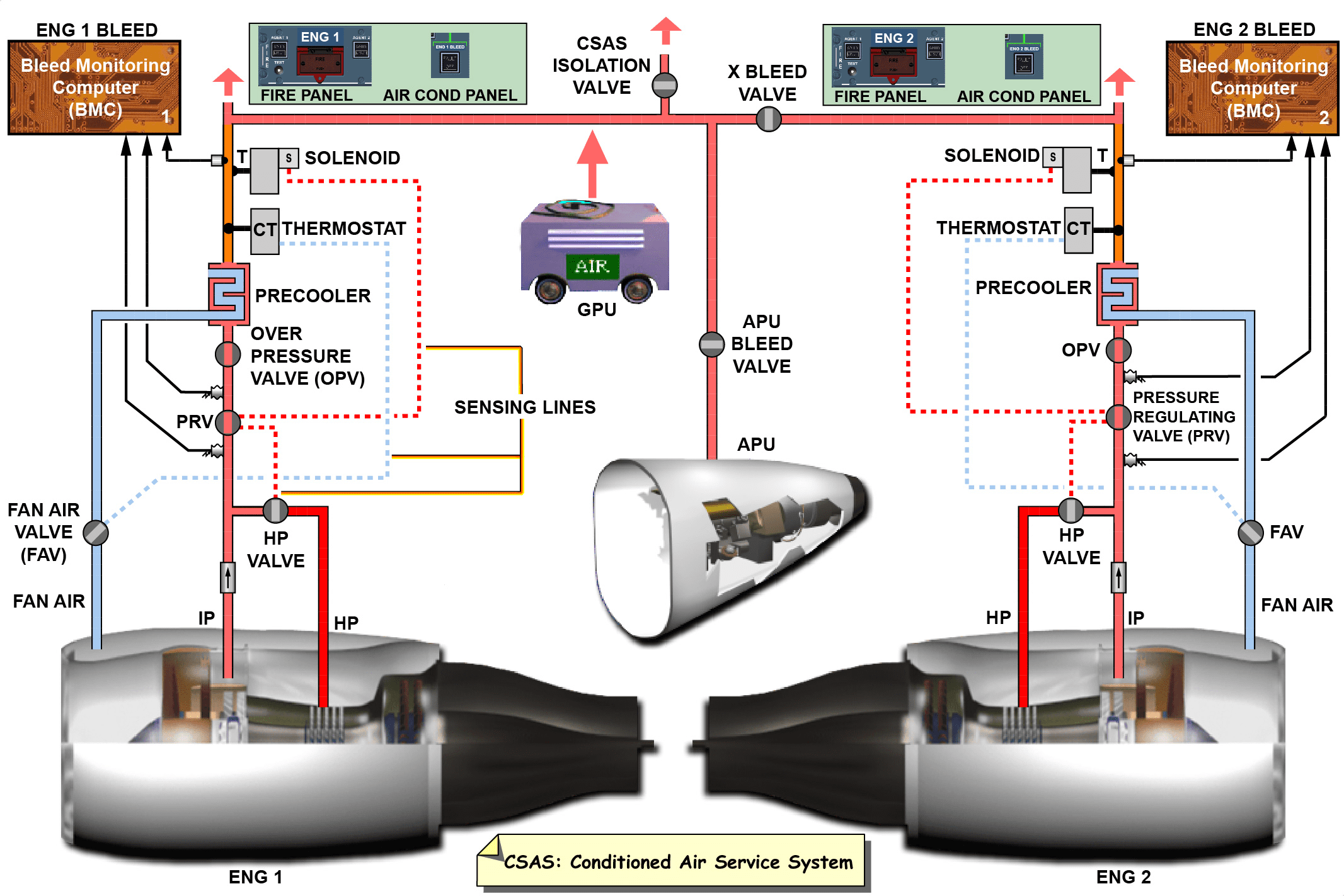
A. The air supply distribution system controls the temperature and pressure of supply air from the engines. It also moves supply air from the pneumatic sources (engines, auxiliary power unit, and ground air connectors) to the systems that use the air in the airplane.
供气分配系统控制来自发动机的供气温度与压力,并将来自气源(发动机、辅助动力装置及地面供气接口)的空气输送至飞机各用气系统。
B. Pneumatic Air Sources
(1) The primary source of air for the pneumatic system is air from the engine compressors. Air is removed from the left and right engines at intermediate and high stage compressor section connections.
(2) Two other sources are the auxiliary-power unit (APU) and ground air supplied to the airplane through its ground-air connectors. The APU supplies compressed air to the airplane systems on the ground or as a secondary source in flight. The ground-air-supply connectors supply compressed air to the airplane systems from a ground pneumatic cart. The ground connectors are on the bottom left side of the fuselage. They connect to the air-supply-body-crossover duct.
B. 气源系统
(1) 气动系统主要气源来自发动机压缩机。空气从左右发动机的中压级与高压级压缩机段接口处提取。
(2) 其他两类气源为辅助动力装置(APU)及通过地面空气连接器输入的地面气源。APU在地面为飞机系统提供压缩空气,飞行中则作为备用气源。地面空气连接器通过地面气源车为飞机系统供气,该连接器位于机身左下方,与空气供应机体交叉管道相连。
C. Pneumatic Air Requirements
(1) The pneumatic system supplies air for these airplane systems:
(a) Airplane pressurization and air conditioning
(b) Wing leading edge and engine-cowl-thermal-anti-ice protection
(c) Forward and aft cargo area heat systems
(d) Windshield-rain repellent system for pressurization
(e) Air-driven-hydraulic-pump operation and reservoir pressurization
(f) Potable-water tank pressurization
(g) Total-air-temperature-probe heat.
C. 气动系统空气需求
(1) 气动系统为下列飞机系统供气:
(a) 客舱增压与空调系统
(b) 机翼前缘及发动机整流罩防冰系统
(c) 前后货舱供暖系统
(d) 增压风挡防雨系统
(e) 气动液压泵操作及储液罐增压
(f) 饮用水箱增压
(g) 总空气温度探头加热。
D. Air Supply Distribution
(1) The air-supply-distribution ducts move supply air to the airplane systems that use the air. Engine ducts , pressure, and temperature control components, provide pressure and temperature controlled air from the engine to the main supply ducts.
D. 空气分配系统
(1) 空气分配管道将供气输送至各用气系统。发动机管道及压力温度控制组件负责将发动机产生的压力与温度控制空气输送至主供气管道。
E. Air Supply Control
(1) Switch/lights on the pilots’-overhead panel P5 control the APU shutoff valve, isolation valves (left, right, and center) and engine-air-control valves. The air-supply-control card supplies power and logic circuitry for control of engine-air-control valves.
E. 空气供应控制
(1) 飞行员顶板P5上的开关/指示灯控制辅助动力装置(APU)关断阀、隔离活门(左/右/中)及发动机空气控制活门。空气供应控制板为发动机空气控制活门提供电源及逻辑电路。
F. Engine Air Supply System (Figure 2)
(1) Each engine-air-supply system includes these components:
(a) Pneumatic ducts
(b) Intermediate-pressure-check valve
(c) High-pressure-shutoff valve (HPSOV)
(d) High-pressure-shutoff-valve controller (HPC)
(e) Pressure-regulating valve (PRV)
(f) Pressure-regulating-valve controller (PRVC)
(g) Air-supply precooler
(h) Fan-air-modulating valve
(i) Fan-air-temperature sensor
(j) Pressure-regulating-and-shutoff valve (PRSOV)
(k) A printed circuit card to give electrical power and control logic.
F. 发动机空气供应系统 (图2)
(1) 每套发动机空气供应系统包含以下组件:
(a) 气动管道
(b) 中压止回阀
(c) 高压关断活门(HPSOV)
(d) 高压关断活门控制器(HPC)
(e) 调压活门(PRV)
(f) 压力调节活门控制器 (PRVC)
(g) 供气预冷器
(h) 风扇空气调节活门
(i) 风扇空气温度传感器
(j) 压力调节与关断活门 (PRSOV)
(k) 提供电力及控制逻辑的印刷电路板。
(2) The engine-air-supply system controls the pressure, temperature and flow of engine bleed air. Air is removed from the engine at three 15th-stage-bleed connections and at two 8th-stage-bleed connections. (The engine air supply system controls the pressure, temperature and flow of engine bleed air. Air is bled off the engine at four 15th stage bleed ports and at two 8th stage bleed ports. At low power settings, the 15th stage engine compressors provide engine bleed air. At high power settings, 8th stage engine bleed air is used.
(2) 发动机供气系统控制发动机引气压力、温度及流量。空气从发动机15级引气接口(3处)及8级引气接口(2处)引出。(发动机供气系统控制发动机引气压力、温度及流量。空气从发动机15级引气口(4处)及8级引气口(2处)引出。低功率状态下,第15级发动机压缩机提供引气;高功率状态下则使用第8级发动机引气。
(3) At low engine power levels, the 15th-stage-engine compressors supply engine bleed air. At high power levels, 8th stage engine (120 psi) bleed air is used. At low power levels, when air is bled off the 15th stage connections, the intermediate-pressure-check valve keeps air out of the 8thstage-engine connections. When engine high stage pressure increases to 105±5 psi, the HPC closes the HPSOV.
(3) 低功率运行时,第15级发动机压缩机供应引气;高功率运行时则采用第8级发动机(120 psi)引气。在低功率状态下,当空气从第15级接口引出时,中压止回活门防止空气进入第8级发动机接口。当发动机高压级压力升至105±5 psi时,高压控制活门(HPC)关闭高压/中压活门(HPSOV)。
(4) Eight stage air then passes through the check valve and supplies necessary air. Eighth stage and 15th stage air moves to the HP/IP manifold. The HP/IP manifold takes air from The 15th and the 8th stage ducts and sends it out in one duct. This duct will let air move through the ducts to the PRV which keeps air pressure to 64±5 psi. Engine air next will pass through the air-supply precooler. The precooler is an air-to-air heat exchanger which uses fan air for cooling.
(4) 第8级空气随后通过止回活门(单向活门)输送所需空气。第8级与第15级空气汇入高压/中压歧管。高压/中压歧管汇集第15级与第8级导管的空气,通过单一导管输出。该导管将空气输送至压力调节活门(PRV),维持64±5 psi的压力。随后发动机空气流经空气供应预冷器——该预冷器采用风扇空气冷却的空气-空气热交换器。
(5) The fan air temperature sensor, found in the strut PRSOV compartment, looks at precooler output-air temperature. The sensor controls the fan-air-modulating valve which in turn controls the amount of cooling air to the precooler. The fan-air-temperature- sensor works to keep precooler-output temperature at 2048C±178C (4008F±308F).
(5) 位于支柱PRSOV舱室的风扇空气温度传感器监测预冷器出口空气温度。该传感器控制风扇空气调节活门,进而调节输送至预冷器的冷却空气量。风扇空气温度传感器的作用是将预冷器出口温度维持在204±17℃(400±30℉)。
(6) Air from the precooler flows through pneumatic ducts to the PRSOV. The duct that is below the PRSOV has a device in it to mix the air.The air is mixed to make sure that the temperature is the same in all parts of the duct.
(6) 来自预冷器的空气通过气动管道输送至PRSOV。位于PRSOV下方的管道内设有空气混合装置,通过混合确保管道各零件温度均匀。
(7) The PRSOV contains a temperature controller which keeps bleed air temperature to less than 252℃ (485℉). At 232℃±4℃(442℉±7℉) the valve moves toward the closed position, and at 255℃±4℃ (499℉±7℉) the valve fully closes. The valve also contains a pressure controller which keeps downstream pressure at 40±10 psi.
(7) PRSOV包含温度控制器,将引气温度维持在252℃(485℉)以下。当温度达到232℃±4℃(442℉±7℉)时,活门开始向关闭位置移动;达到255℃±4℃(499℉±7℉)时活门完全关闭。该活门还包含压力控制器,将下游压力维持在40±10 psi。
(8) After leaving the PRSOV, supply air takes one of three paths. Bleed air may enter the strut hydraulic reservoirs. It may move outboard along the wing leading edge anti-ice ducts. Or it may move inboard through the wing leading edge ducts. Air that goes inboard enters the air-supplybody-crossover duct. Isolation valves in the body crossover duct stay closed during normal flow.
(8) 离开PRSOV后,供气可选择三条路径:- 进入支柱液压油箱- 沿机翼前缘防冰管道向外侧流动- 或通过机翼前缘管道向内侧流动向内侧流动的气体进入机身交叉管道。正常状态下,该管道的隔离活门保持关闭。
(9) Usually both engines supply air to the system. Air from each engine flows through an isolationbypass-check valve and meets at the joint of the APU air supply duct and the body crossover duct. It then flows aft through the center-isolation valve and the APU air supply duct. The air is then used by the hydraulic reservoir, aft cargo heat, bulk cargo heat and potable water system. Air also flows from the body crossover duct for air conditioning purposes (SUBJECT 21-51-00).
(9) 通常两台发动机均向系统供气。来自各发动机的空气经隔离旁通止回活门汇合于辅助动力装置(APU)供气管与机身交叉管的连接处,随后通过中心隔离活门及APU供气管向后流动。该气流用于液压油箱、后货舱加热、大宗货物舱加热及饮用水系统。机身交叉管道的空气亦用于空调系统(参见21-51-00章)。
(10) The APU check valve keeps engine air from entering the APU.
(10) APU止回活门防止发动机空气进入辅助动力装置。
(11) One source (one engine, APU or ground cart) can supply all the pneumatic air needs. If only one source is available, the isolation valves are opened and air flows to all the systems.The fan air modulating valve is opened and closed by air pressure from the fan air temperature sensor.The valve is spring loaded open. If either bleed air supply or signal pressure is lost from the fan air temperature sensors the valve moves open.
(11) 单一气源(发动机、APU或地面供气车)可满足全部气动需求。当仅有一气源可用时,开启隔离活门即可向所有系统供气。风扇空气调节活门由风扇空气温度传感器的气压控制打开和关闭。该活门采用弹簧预开式设计。当风扇空气温度传感器出现引气供应中断或信号压力丢失时,活门将自动开启。
![图片[7]-773284 FAN AIR TEMPERATURE SENSOR-航修札记](https://www.aeroacm.com/wp-content/uploads/2025/11/20251111222851801-word-image-10796-7.png)
![图片[8]-773284 FAN AIR TEMPERATURE SENSOR-航修札记](https://www.aeroacm.com/wp-content/uploads/2025/11/20251111222851890-word-image-10796-8.png)
H. Fan-Air-Temperature Sensor (Figure 12) EFFECTIVITY BEJ 005, 006, 301-999
(1) The fan-air-temperature sensor is found on the duct below the PRSOV on the right side of the duct. The sensor body contains a lever and crank operated by a bimetallic-temperature probe. The temperature probe extends into the duct. Two pressure switches and a temperature sensor provide information to the BITE system.
(2) The fan-air-temperature sensor controls the servo pressure that controls the fan air valve. The bimetallic-temperature probe in the pneumatic duct connects the compensating springs to the control lever. Temperature variations in the duct cause the temperature probe to produces force changes on the control lever. The movement of the control lever causes the poppet to open or close. The poppet movement adjusts the amount of control air bled to ambient. This will changes the pressure signal to the fan-air-modulating valve. Servo pressure also flows through a restrictor onto a sensor diaphragm. This diaphragm is connected to the control lever and keeps the lever in balance.
(3) When the temperature goes up the poppet will open, servo pressure Will vent and the fan-air modulating valve opens. Below 187℃ (369℉), the fan air valve is closed and all temperature control is removed. At 221℃ (430℉) or higher the fan air valve is full open A ball poppet in the pressure supply line bleeds off excess pressure. This gives a regulated air supply to the sensor and decreases supply pressure variations.
H. 风扇-空气-温度传感器(图12) 适用 BEJ 005, 006, 301-999
(1) 风扇进气温度传感器位于管道下方、PRSOV右侧。传感器主体内含由双金属温度探头驱动的杠杆与曲柄机构,温度探头延伸至风管内部。两个压力开关与温度传感器共同向BITE系统提供数据。
(2) 风扇进气温度传感器控制着调节风扇空气活门的伺服压力。气动管道中的双金属温度探头将补偿弹簧与控制杠杆相连。管道内温度变化导致温度探头对控制杠杆产生力值变化,控制杠杆的位移进而控制阀芯的启闭。阀芯运动调节泄放至环境的控制气量,从而改变输送至风扇空气活门的压力信号。伺服压力同时流经节流装置作用于传感器膜片,该膜片与控制杆相连以维持杆体平衡。
(3) 当温度上升时,阀芯开启,伺服压力泄放,风扇空气活门随之打开。低于187℃(369℉)时,风扇空气活门关闭且所有温度控制功能解除。当温度达到221℃(430℉)或更高时,风扇空气活门完全开启。压力供给管路中的球形阀芯将释放过剩压力,从而为传感器提供稳定气源并减少供气压力波动。
![图片[9]-773284 FAN AIR TEMPERATURE SENSOR-航修札记](https://www.aeroacm.com/wp-content/uploads/2025/11/20251111222852469-word-image-10796-9.png)


暂无评论内容