一、名称
FLOW CONTROL VALVE
流量控制活门(FCV)
二、件号
964A0000-03,-04 Amdt A,-05,-05 Amdt A,-05 Amdt B,-06,964F0000-01,-02,-01 Amdt A,-01 Amdt B
三、章节号
21-51-51
四、适用机型
A330/A340
五、系统
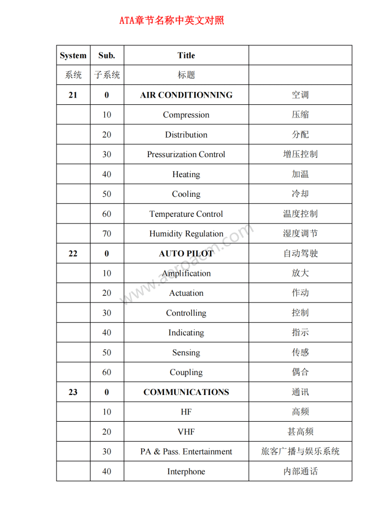
21 AIR CONDITIONING
空调
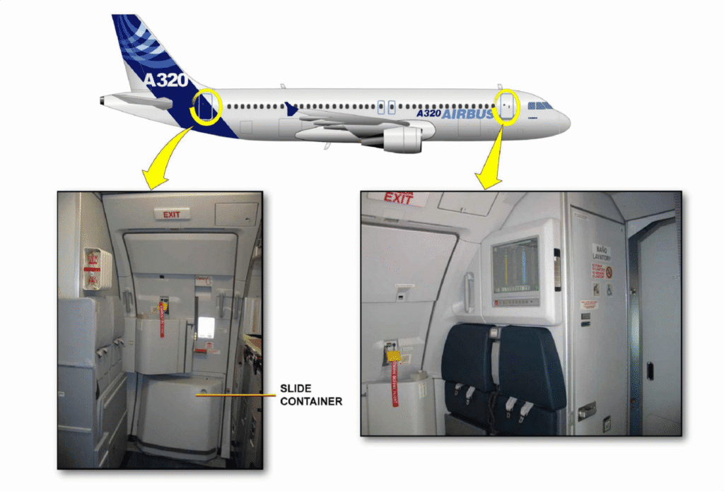
六、安装位置
空调舱
![图片[1]-964A/F FLOW CONTROL VALVE(FCV)-航修札记](https://www.aeroacm.com/wp-content/uploads/2025/09/word-image-9073-1-1.png)
![图片[2]-964A/F FLOW CONTROL VALVE(FCV)-航修札记](https://www.aeroacm.com/wp-content/uploads/2025/09/word-image-9073-2-1.png)
![图片[3]-964A/F FLOW CONTROL VALVE(FCV)-航修札记](https://www.aeroacm.com/wp-content/uploads/2025/09/word-image-9073-3-1.png)
![图片[4]-964A/F FLOW CONTROL VALVE(FCV)-航修札记](https://www.aeroacm.com/wp-content/uploads/2025/09/word-image-9073-4-1.png)
七、部件原理
Description
描述
A. General Description
一般说明
(1) The main purpose of the Flow Control Valve (FCV) is to ensure a constant rate of air flow in an air conditioning system. It also allows the air flow to be limited or completely stopped if necessary or in the case of an anomaly.
流量控制活门(FCV)的主要目的是确保空调系统中的空气流量保持恒定。必要时或出现异常情况时,它还允许限制或完全停止空气流动。
B. Detailed Description (Refer to Figure 3)
详细说明 (Refer to Figure 3)
The Flow Control Valve essentially consists of:
流量控制活门主要由以下部件组成:
– a pneumatic regulator,
气动调节器
– an electropneumatic regulator,
电气调节器
– a butterfly valve,
蝶板
– electrical and pneumatic connecting parts.
电气和气动连接部件。
![图片[5]-964A/F FLOW CONTROL VALVE(FCV)-航修札记](https://www.aeroacm.com/wp-content/uploads/2025/09/word-image-9073-5-1.png)
2. Operation
操作运行
A. General (Refer to Figure 4)
概述(Refer to Figure 4)
The Flow Control Valve ensures the following functions for the cooling pack:
流量控制活门确保冷却pack具有以下功能:
– air flow regulation,
空气流量调节
– air flow shutdown if required,
必要时关闭气流,
– overheat protection detected at the air cycle machine’s compressor outlet,
在空气循环机的压缩机出口处检测到过热保护
– sufficient inlet pressure for proper air machine operation.
足够的入口压力,以保证空气循环机正常运转
These different functions are ensured by a butterfly type valve controlled by a pneumatic actuator.
这些不同的功能由气动作动器控制的蝶板来保证。
(1) Air Flow Regulation
流量调节
There are two air flow regulation operating modes:
有两种流量调节操作模式:
– electropneumatic regulation mode (main mode),
电-气调节模式(主模式),
– pneumatic regulation mode (back up mode).
气动调节模式(备用模式)。
There is a selector switch (S2), controlled by the pack controller, for selecting the regulation mode. In the event of an electrical failure, the selector enables operation in pneumatic mode.
有一个由pack控制器控制的选择开关(S2),用于选择调节模式。在发生电气故障时,选择器使其进入气动模式。
(2) Air Flow Shutdown
气流关闭
Air flow shutdown is controlled by a solenoid assembly (S1) which vents the pneumatic actuator chamber. The ON/OFF logic of this solenoid assembly allows air flow regulation even in the event of an electrical failure.
气流关闭由电磁阀组件(S1)控制,该组件气动作动器腔室排出。此电磁阀组件的ON/OFF逻辑允许在发生电气故障时调节气流。
(3) Overheat Protection
过热保护
This protection is accomplished by means of a pneumatic overheat detector (CPNOH) connected to the actuator chamber. If the temperature increases over a threshold, the butterfly valve closes.
这种保护是通过连接至作动器室的气动过热探测器(CPNOH)(PN:766A/B)来实现的。如果温度超过阈值,蝶板将关闭。
B. Detailed Operation
详细操作
(1) Regulation Mode Selection
调节模式选择
The regulation mode is selected by the mode selector (S2) according to the following logic:
调节模式由模式选择器(S2)根据以下逻辑进行选择:
– S2 energized: electropneumatic regulation,
S2通电:电气调节,
– S2 de-energized: pneumatic regulation.
S2断电:气动调节。
When energized, the solenoid acts on the pin which pushes the ball against the seat . This closes the pneumatic regulation circuit. When the solenoid is no longer energized, a return spring pushes the ball back to its initial position. The electropneumatic regulation circuit is then closed.
当通电时,电磁阀作用于销钉,将球顶着阀座。这将关闭气动调节回路。当电磁阀不通电时,复位弹簧将球体推回其初始位置。此时,电-气调节回路被闭合。
(2) Electropneumatic Regulation
电-气调节
Electropneumatic regulation is the main operating mode of the flow control valve. This electropneumatic regulation is ensured by a pressure regulator associated with a torque motor.
电空调节是流量控制活门的主要操作模式。该电气调节由与扭矩马达相连的压力调节器来保证。
(a) Pressure Regulation
压力调节
The pressure regulator maintains at a constant pressure upstream from the jet (G9), the upstream air pressure (P) which is bled off by means of an trailing edge probe fitted on the valve body. This reference value is determined by the position of the clapper with respect to its seat. The position of the clapper is permanently modified by the diaphragm which moves under the action of the reference air passing through jet (G8). The reference air then supplies the actuator chamber after passing through jet (G9). The reference value can be adjusted by acting on the regulator’s adjustment screw.
压力调节器将通过限流孔(G9)的上游压力保持恒定,上游压力(P)通过安装活门本体上的后缘探头引气。该基准值由阀芯相对于阀座的位置决定。膜片在通过限流孔(G8)的基准空气压力作用下移动,从而永久性地改变阀芯的位置,随后基准气压经过限流孔(G9)进入作动器腔室。可通过调节调节器的调节螺钉来调整基准值。
(b) The Torque Motor
扭矩马达
Using the differential pressure measured on the valve between P1 and P2 by the differential pressure sensor (DPS), the pack controller (PC) controls the torque motor. Rotation of the torque motor’s rotor modifies the angular position of the quadrant with respect to a venting nozzle thus creating a variable leakage downstream from the jet (G9) in order to modify the actuator pressure with respect to the flow demand.
通过差压传感器(DPS)在活门P1与P2之间测得的压差值,pack控制器(PC)对扭矩马达进行控制。当扭矩马达转子旋转时,其转子会改变挡板(quadrant扇形体)相对于排气喷嘴的角度位置,从而在限流孔(G9)下游形成可变泄漏量,进而根据流量需求动态调节作动器压力。
(3) Pneumatic Regulation
气动调节
Pneumatic regulation is the flow control valve’s safety mode in case of electrical power on main regulation failures. The pneumatic regulation device comprises a pressure regulator and a flow detector designed to provide a stable nominal mass flow of 100%. The pneumatic regulator creates a constant flow through a fixed jet (G7) proportional the nominal flow through the valve; this nominal flow varies with the cabin pressure. It controls the pressure in the pneumatic actuator by comparing the pressure difference between the valve inlet (P’1) and the venturi throat (P’2).
气动调节是流量控制活门在主调节器发生故障且电源接通时的安全模式。该装置包含压力调节器和流量检测器,旨在提供稳定恒定的标称质量流量(100%)。气动调节器通过固定限流孔(G7)产生恒定流量,其流量与活门标称流量成比例——而标称流量会随客舱压力变化。该系统通过比较活门入口(P’1)与文氏管喉部(P’2)之间的压差来调控气动作动器的压力。
(4) Air Flow Shutdown
气流关闭
A Solenoid Assembly (S1) stops the air flow if this is required. Through the action of a spring, a ball crimped to a plunger closes an air vent when the solenoid is not energized. Solenoid energization draws the plunger into the coil. The ball is no longer in contact with its seat, and the air is vented. Since the chamber of the pneumatic actuator is no longer supplied, the butterfly valve closes. Two microswitches indicate that the butterfly is in the fully closed position.
电磁阀组件(S1)可根据需要停止气流。在电磁阀未通电时,通过弹簧的作用,一个与衔铁压紧的球关闭排气口。通电后衔铁被吸入线圈,球体脱离阀座接触,空气随之排出。由于气动作动器腔室失去气源,蝶板随即关闭。两个微动开关会实时监测蝶板是否处于完全关闭状态。
![图片[6]-964A/F FLOW CONTROL VALVE(FCV)-航修札记](https://www.aeroacm.com/wp-content/uploads/2025/09/word-image-9073-6.png)
八、工作参数
![图片[7]-964A/F FLOW CONTROL VALVE(FCV)-航修札记](https://www.aeroacm.com/wp-content/uploads/2025/09/word-image-9073-7.png)
九、在飞机中的功能与互联
1 . General(Ref. Fig. 001)
概述
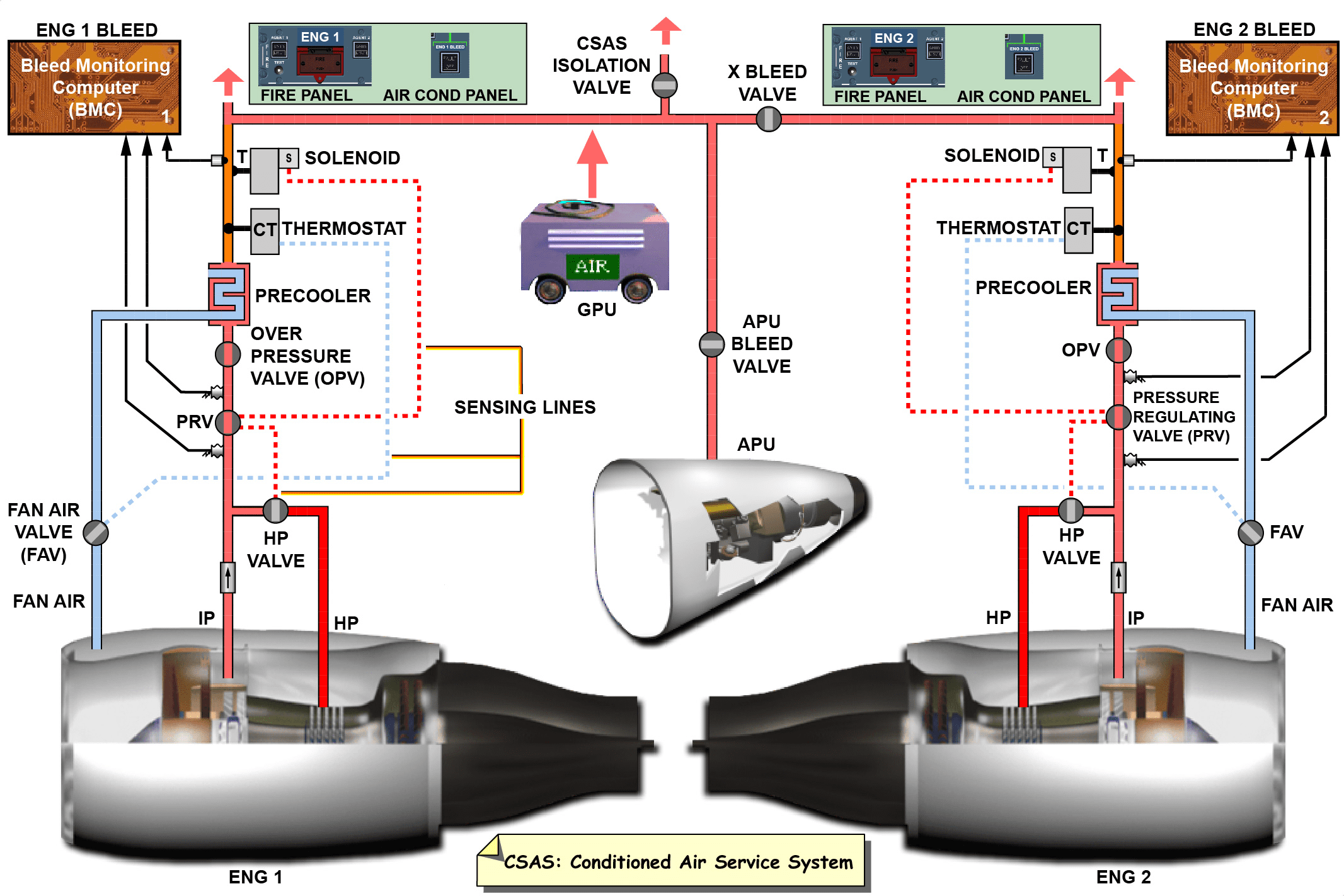
The air conditioning system keeps the air in the pressurized fuselage compartments at the correct pressure, temperature and freshness. In normal conditions, the pneumatic system supplies air to the air conditioning system from:
– the main engine compressors,
– the APU compressor,
– a high-pressure ground-air supply-unit.
The hot compressed air is cooled, conditioned and supplied to the fuselage compartments and then discharged overboard through the outflow valves. You can also supply conditioned air to the distribution system through a low pressure ground-connection.
空调系统负责维持加压机身舱室内的空气压力、温度和湿度处于最佳状态。在常规工况下,气动系统通过以下渠道为空调系统供气:
-主发动机压缩机、
-辅助动力装置(APU)压缩机、
-高压地面供气。
经过冷却调节的高温压缩空气被输送至机身舱室后,最终通过外排活门排出至机外。此外,您还可以通过低压地面连接口向分配系统输送经调节的空气。
2 . System Description
系统描述
The air conditioning system gives satisfactory values of pressure, temperature and freshness of the air in the pressurized fuselage. It has the subsequent subsystems:
– distribution,
– pressurization control,
– heating,
– air cooling,
– temperature control.
空调系统为加压机身内的空气提供了令人满意的压力、温度和新鲜度值。它有以下子系统:
-分配,
-加压控制,
-加热,
-空气冷却,
-温度控制。
A. Distribution System
分配系统
The distribution system (Ref. 21-20-00) permits temperature controlled and conditioned air from the air conditioning packs to flow through the pressurized fuselage.
分配系统(Ref. 21-20-00)允许来自空调pack的温度控制和调节空气流经加压机身。
B. Pressurization Control System
加压控制系统
The pressurization control system (Ref. 21-30-00) controls the pressure in the fuselage. It operates fully automatically and has a manual backup.The pressure change rate is controlled to give satisfactory pressure values of safety and comfort for the passengers and crew.
加压控制系统(Ref. 21-30-00)控制机身内的压力。该系统完全自动运行,具有手动备份功能。通过控制压力变化率,为乘客和机组人员提供满意的安全和舒适压力值。
C. Heating System
加热系统
The heating system (Ref. 21-40-00) increases the temperature of the air in the lower fuselage.
加热系统(Ref. 21-40-00)可提高下机身内空气的温度。
D. Air Cooling System
空气冷却系统
The air cooling system (Ref. 21-50-00) decreases the temperature of the hot bleed air from the pneumatic system. It also reduces the quantity of water in the hot bleed air. Emergency air is supplied if there is a failure in the two air conditioning packs.
空气冷却系统(Ref. 21-50-00)降低来自气动系统的热引气的温度。它还减少热引气中的水量。如果两个空调pack发生故障,则提供紧急空气。
![图片[9]-964A/F FLOW CONTROL VALVE(FCV)-航修札记](https://www.aeroacm.com/wp-content/uploads/2025/09/word-image-9073-8.png)
E. Temperature Control System
温度控制系统
The temperature control system (Ref. 21-60-00) controls the temperature of the air supplied to the cockpit and cabin. You can adjust the temperature in the cockpit and the cabin.
温度控制系统(Ref. 21-60-00)控制供给驾驶舱和客舱的空气温度。您可以调节驾驶舱和客舱内的温度。
AIR COOLING – DESCRIPTION AND OPERATION
空气冷却-描述和操作
1 . General
概述
Air Cooling System
空气冷却系统
The air cooling system decreases the temperature of the hot bleed air from the pneumatic system. It also reduces the quantity of water in the hot bleed air.Emergency air is supplied if there is a failure in the two air conditioning packs.
空气冷却系统降低了来自气动系统的热引气的温度,同时减少了热引气中的水量。如果两个空调pack发生故障,则会提供应急空气。
2 . System Description
系统描述
The air cooling system has the subsequent subsystems:
– flow control and indicating,
– air conditioning packs,
– pack control and indicating,
– emergency ram-air inlet.
空气冷却系统具有以下子系统:
-流量控制和指示,
-空调pack,
-包控制和指示,
-紧急冲压空气入口。
A. Flow Control and Indicating System
流量控制和指示系统
The flow control and indicating system (Ref. 21-51-00) controls the quantity of hot bleed air that flows to the air conditioning packs and the trim air valves. Flow control valves adjust the flow and flow sensors send flow data to the pack controllers.
流量控制和指示系统(Ref. 21-51-00)控制流向空调组件和调节空气阀的热引气量。流量控制活门调节流量,流量传感器将流量数据发送至pack控制器。
B. Air Conditioning Packs
空调pack
The two air conditioning packs (Ref. 21-52-00) decrease the temperature and the water contained in the hot bleed air from the pneumatic system. Heat exchangers decrease the temperature of the air. An air cycle machine first compresses the air and then expands it. A condenser condenses the water in the air and a water extractor removes the water.
两个空调pack(Ref.21-52-00)降低温度并减少气动系统中热引气中的水分。热交换器降低空气温度。空气循环机首先压缩空气,然后膨胀空气。冷凝器将空气中的水分凝结,水分离器去除水分。
C. Pack Control and Indicating System
Pack控制和指示系统
The pack control and indicating system (Ref. 21-53-00) controls the pack outlet temperature and sets its maximum and minimum limits. Pack controllers control the system. Air inlet and outlet flap actuators adjust the quantity of ram air flow to decrease the temperature of the air conditioning packs. Temperature and pressure sensors monitor the system.
Pack控制和指示系统(Ref.21-53-00)控制压缩机出口温度并设置其最大和最小限制范围。Pack控制器控制该系统。空气入口和出口挡板作动器调节冲压空气流量,以降低空调压缩机的温度。温度和压力传感器监测该系统。
D. Emergency Ram-Air Inlet
应急冲压空气进气口
The emergency ram-air inlet (Ref. 21-55-00) gives a flow of fresh air through the aircraft if there is a failure in both air conditioning packs. A ram air actuator extends and retracts the emergency ram-air inlet. Check valves prevent the flow of air in the opposite direction.
如果两个空调pack都发生故障,应急冲压空气进气口(Ref. 21-55-00)可使新鲜空气流经飞机。冲压空气作动器伸缩紧急冲压空气进气口。单向活门防止空气反向流动。
FLOW CONTROL AND INDICATING – DESCRIPTION AND OPERATION
流量控制和指示器-描述和操作
1 . General
概述
The flow control and indicating system controls the quantity of hot bleed air that flows to the air conditioning packs and trim air valves. Flow control valves adjust the flow and flow sensors send flow data to the pack controllers.
流量控制和指示系统控制流向空调pack和配平空气活门的热引气量。流量控制活门调节流量,流量传感器将流量数据发送至pack控制器。
3 . System Description
系统描述
A. General (Ref. Fig. 004)
概述
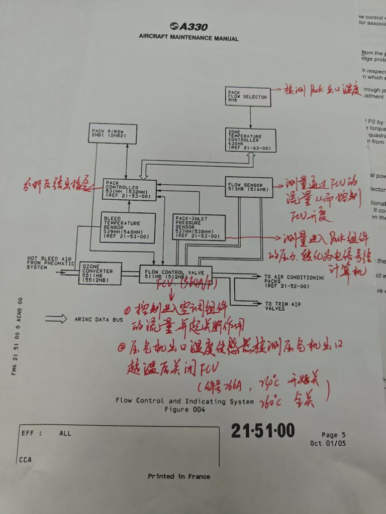
The hot bleed air from the pneumatic system flows through the ozone converters 5511HB (5512HB). It then flows through the flow control valves 511HB (512HB) to the air conditioning packs and the trim air valves.The pushbutton-switches PACK1 (2HB1) and PACK2 (2HB2) control the air-flow to the air conditioning packs 521HH and 522HH.
气动系统中的热引气流经臭氧转换器5511HB(5512HB),然后流经流量控制活门511HB(512HB)到达空调pack和配平空气活门。按钮开关PACK1(2HB1)和PACK2(2HB2)控制流向空调pack521HH和522HH的气流。
![图片[10]-964A/F FLOW CONTROL VALVE(FCV)-航修札记](https://www.aeroacm.com/wp-content/uploads/2025/09/word-image-9073-9.png)
The legends of the pushbutton-switches show FAULT if there is a failure or if an air conditioning pack 521HH (522HH) does not operate. The pushbutton-switches are installed on the panel 225VU in the cockpit. The PACK FLOW selector 8HB controls the flow of hot bleed air through the air conditioning packs 521HH (522HH). It adjusts the flow of air through the flow control valves 511HB (512HB). It is installed on the panel 225VU in the cockpit.
当出现故障或空调组件521HH(522HH)未启动时,按钮开关会显示故障提示。这些按钮开关安装在驾驶舱的225VU控制面板上。热交换器流量选择器8HB负责调控空调组件521HH(522HH)的热交换空气流量,通过调节流量控制活门511HB(512HB)来实现。该装置同样安装在驾驶舱的225VU控制面板上。
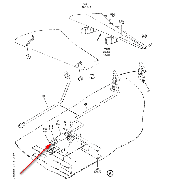
The flow control valves 511HB (512HB) are installed in the unpressurized area of the belly fairing near the air conditioning packs 521HH (522HH). They adjust the quantity of hot bleed air that flows to the air conditioning packs and the trim air valves. The pack controllers 531HH (532HH) control the position of the flow control valves. If they close, the flow of hot bleed air to the air conditioning packs and trim air valves stops. If there is no electrical power, the flow control valves permit a flow of 120% in pure pneumatic control mode.
流量控制活门511HB(512HB)安装在机腹整流罩未加压区域,靠近空调组件521HH(522HH)。这些活门用于调节流向空调组件和配平空气活门的热引气量。空调组件控制器531HH(532HH)负责调控流量控制活门的位置——当活门关闭时,流向空调组件和配平空气活门的热引气就会停止。如果没有电源,则流量控制活门允许在纯气动控制模式下进行120%的流量。
The flow sensors 513HB (514HB) are installed in the unpressurized area of the belly fairing near to the air conditioning packs 521HH (522HH). They measure the difference in pressure (delta p) between the two pressure ports in each flow control valve. Delta p data is sent to the applicable pack controller 531HH (532HH).
流量传感器513HB(514HB)安装在靠近空调机组521HH(522HH)的腹部整流罩非加压区域,用于测量每个流量控制活门中两个压力端口之间的压差(Δp)。压差数据将发送至对应的空调机组控制器531HH(532HH)。
– For Ozone Converter with Part number 40997003 and previous:
-对于件号为40997003及之前型号的臭氧转换器:
The ozone converters 5511HB (5512HB) are installed in the unpressurized area of the belly fairing near the flow control valves 511HB (512HB). They catalytically remove the ozone from the hot bleed air before it flows to the air conditioning packs or the trim air valves.
臭氧转换器5511HB(5512HB)安装在靠近流量控制活门511HB(512HB)的腹部整流罩的非加压区域。它们在热引气气流向空调pack或配平空气活门之前,通过催化去除臭氧。
– For Ozone Converter with Partnumber 44142002 and subsequent:
-对于部件号为44142002及后续型号的臭氧转换器:
The ozone converters 5511HB (5512HB) are installed in the unpressurized area of the belly fairing near the flow control valves 511HB (512HB). They catalytically remove the ozone and Volatile Organic Components (VOC) from the hot bleed air before it flows to the air conditioning packs or the trim air valves.
臭氧转换器5511HB(5512HB)安装在靠近流量控制活门511HB(512HB)的腹部整流罩非加压区域。它们在热引气流向空调pack或配平空气活门之前,通过催化作用去除热引气中的臭氧和挥发性有机化合物(VOC)。
5 . Interface
接口
A. Flow Control and Indicating System Interfaces
流量控制和指示系统接口
The flow control and indicating system has interfaces with:
流量控制和指示系统具有以下接口:
– the pneumatic system,
气动系统
– the pack controllers,
Pack控制器
– the zone temperature controller,
区域温度控制器
– cabin pressure controllers,
客舱压力控制器
– flight warning system,
飞行警报系统
– avionics equipment ventilation controller,
航空电子设备通风控制器
– the air conditioning packs,
空调pack
– the trim air valves,
配平空气活门
– the Engine-Interface Vibration-Monitoring Units (EIVMUs),
发动机接口振动监测装置(EIVMU),
– the light test system,
光测试系统
– the DITCHING P/BSW,
DITCHING P/BSW
– the engine start logic relays,
发动机起动逻辑继电器,
– the engine FIRE P/BSWs,
发动机FIRE P/BSWs,
– the ventilation controller,
通风控制器
– pneumatic compressor-overheat sensors,
气动压缩机过热传感器
– the bleed temperature sensors,
引气温度传感器
– the pack-inlet pressure sensors.
Pack进气口压力传感器。
– the bleed system,
引气系统
– the bleed monitoring computers (BMC),
引气监测计算机(BMC)
– the AFT galley heating.
后厨房加热
B. Pneumatic System Interface
气动系统接口
The hot bleed air that flows through the flow control and indicating system comes from the pneumatic system (Ref. 36-00-00).
流过流量控制和指示系统的热引气来自气动系统(Ref.36-00-00)。
C. Pack Controller Interface
Pack控制器接口
The pack controllers 531HH (532HH) (Ref. 21-53-00) control the flow control and indicating system. They send flow signals to the flow control valves 511HB (512HB) and monitor the flow sensors 513HB (514HB).
Pack控制器531HH(532HH)(Ref.21-53-00)控制流量控制和指示系统。它们向流量控制活门511HB(512HB)发送流量信号,并监测流量传感器513HB(514HB)。
D. Zone-Temperature Controller Interface
区域温度控制器接口
There is an ARINC data bus between the zone temperature controller 630HK (Ref. 21-63-00) and the pack controllers 531HH (532HH) (Ref. 21-53-00).The zone temperature controller sends a demand signal to the pack controllers. The pack controllers calculate the necessary flow from the demand signal.
在区域温度控制器630HK(Ref.21-63-00)和电池组控制器531HH(532HH)(Ref.21-53-00)之间有一个ARINC数据总线。区域温度控制器向电池组控制器发送需求信号。电池组控制器根据需求信号计算出必要的流量。
E. Air-Conditioning Packs Interface
空调pack接口
Some of the hot bleed air flows from the flow control and indicating system to the air conditioning packs (Ref. 21-52-00).
部分热引气来自流量控制和指示系统,流向空调pack(Ref.21-52-00)。
F. Trim-Air Valve Interface
配平空气活门接口
Hot bleed air flows from the flow control and indicating system to the trim air valves 631HK thru 637HK (Ref. 21-63-00). Some of the hot bleed air flows to the trim air valve 438HC (Ref. 21-43-00).
热引气从流量控制和指示系统流向配平空气活门631HK至637HK(Ref.21-63-00)。部分热引气流向配平空气活门438HC(参考21-43-00)。
G. EIVMUs Interface
EIVMUs 接口
The EIVMUs send a signal to the close relays 3HB1 (3HB2) if there is an engine start. The flow control valves 511HB (512HB) close if there is an engine start.
如果发动机起动,EIVMU将向关闭继电器3HB1(3HB2)发送信号。如果发动机起动,流量控制活门511HB(512HB)将关闭。
H. Light-Test System Interface
灯光测试系统接口
When you operate the light test system (Ref. 33-14-00), the FAULT and OFF legends in the PACK 1 P/BSW 2HB1 and the PACK 2 P/BSW 2HB2 come on.
操作灯光测试系统(Ref.33-14-00)时,PACK 1 P/BSW 2HB1和PACK 2 P/BSW 2HB2中的故障和关闭标识灯会亮起。
J. Cross-Feed Valve Interface
Cross-Feed Valve接口(不会翻译,未接触到这个活门)
When the cross feed valve 6HV (Ref. 36-12-00) is not fully closed it sends a signal to the X-feed relay 11HB.
当cross feed valve6HV(Ref. 36-12-00)没有完全关闭时,它会向XX-feed继电器11HB发送信号。
K. DITCHING P/BSW Interface
DITCHING P/BSW接口
When you push the DITCHING P/BSW 13HL (Ref. 21-31-00), the flow control valves 511HB (512HB) close.
当按下DITCHING P/BSW 13HL(Ref.21-31-00)时,流量控制活门511HB(512HB)关闭。
L. Engine Logic-Relays Interface
发动机逻辑继电器接口
The logic relays 27KS (28KS) (Ref. 73-25-00) send signals to the close relays 3HB1 (3HB2). This is a backup function for manual ENG start in case of missing EIVMU.
逻辑继电器27KS(28KS)(Ref.73-25-00)向闭合继电器3HB1(3HB2)发送信号。这是在缺少EIVMU的情况下手动ENG启动的备用功能。
M. Engine FIRE P/BSWs Interface
发动机 FIRE P/BSWs接口
The engine FIRE P/BSWs send a signal to the close relays 3HB1 (3HB2) if there is a fire in an engine. The flow control valves 511HB (512HB) close.
发动机FIRE P/BSWs:如果发动机发生火灾,发动机FIRE P/BSWs将向闭合继电器3HB1(3HB2)发送信号。流量控制活门511HB(512HB)将关闭。
N. Ventilation Controller Interface
通风控制器接口
The ventilation controller 280HN (Ref. 21-28-00) sends a cargo compartment demand signal to the zone temperature controller 630HK (Ref. 21-63-00). This is used to calculate the demand signal sent to the pack controllers 531HH (532HH) (Ref. 21-53-00). The pack controllers calculate the necessary flow signal sent to the flow control valves 511HB (512HB).
通风控制器280HN(Ref. 21-28-00)向区域温度控制器630HK(Ref. 21-63-00)发送货舱需求信号。该信号用于计算发送至包控制器531HH(532HH)(Ref. 21-53-00)的需求信号。Pack控制器根据该信号计算出发送至流量控制活门511HB(512HB)的必要流量信号。
P. Pneumatic-Compressor-Overheat Sensor Interface
气动压缩机过热传感器接口
The flow control valves 511HB (512HB) have a pneumatic interface with the pneumatic compressor-overheat sensors 521HH22 (522HH22) (Ref. 21-53-00).
流量控制活门511HB(512HB)具有与气动压缩机过热传感器521HH22(522HH22)的气动接口(Ref.21-53-00)。
The flow control valves move to a more closed position if the temperature increases too much in the compressor of the air cycle machine 521HH12 (522HH12) (Ref. 21-52-00).
如果空气循环机器521HH12(522HH12)的压缩机中的温度过高,则流量控制活门移动到更关闭的位置(参考21-52-00)。
Q. Bleed Temperature-Sensor Interface
引气温度传感器接口
The bleed temperature sensors 539HH (540HH) (Ref. 21-53-00) send bleed temperature data to the pack controllers 531HH (532HH) (Ref. 21-53-00).The data is used to calculate the flow, which is adjusted in the flow control valve 511HB (512HB).
引气温度传感器539HH(540HH)(Ref.21-53-00)将引气温度数据发送至电池控制器531HH(532HH)(Ref.21-53-00)。该数据用于计算流量,并在流量控制活门511HB(512HB)中进行调整。
R. Pack-Inlet Pressure-Sensor Interface
Pack入口压力传感器接口
The pack-inlet pressure sensors 537HH (538HH) (Ref. 21-53-00) send pressure data to the pack controllers 531HH (532HH) (Ref. 21-53-00). The data is used to calculate the flow, which is adjusted in the flow control valve 511HB (512HB).
Pack入口压力传感器537HH(538HH)(Ref.21-53-00)将压力数据发送至pack控制器531HH(532HH)(Ref.21-53-00)。这些数据用于计算流量,并通过流量控制活门511HB(512HB)进行调节。
6 . Component Description
C. Flow Control Valves(Ref. Fig. 010)
The flow control valves 511HB (512HB) have:
– a venturi,
– a butterfly valve,
– a pneumatic actuator,
– an on/off solenoid,
– a control solenoid (normal/backup flow regulation),
– an electrical pressure regulator,
– a pneumatic pressure regulator (back-up).
The electrical pressure regulator has a torque motor. It drives a cam to change the size of the orifice. The pneumatic pressure regulator has a poppet valve and a relief valve. It receives pressure from the cabin. The pneumatic actuator receives pressure from the pneumatic compressor-overheat sensors 521HH22 (522HH22). There are pressure ports on the valve body for the flow sensors 513HB (514HB). There is a mechanical indicator to show the position of the valve. You can lock the flow control valves in the closed position.
6.部件说明
C.流量控制活门(参考图010)
流量控制活门511HB(512HB)包含以下组件:
-文氏管,
-蝶板,
-气动执行器,
-开/关电磁阀,
-控制电磁阀(正常/备用流量调节),
-电气压力调节器,
-气动压力调节器(备用)。
电气压力调节器配备扭矩马达,通过驱动凸轮改变孔口尺寸。气动压力调节器采用阀座(带阀芯)和泄压阀设计,接收来自驾驶舱的压力信号。气动作动器由气动压缩机过热传感器521HH22(522HH22)(PN:766A)提供压力信号。活门本体上设有供流量传感器513HB(514HB)使用的压力接口,并配有机械指示器显示活门位置。流量控制活门可锁定在关闭状态。
![图片[11]-964A/F FLOW CONTROL VALVE(FCV)-航修札记](https://www.aeroacm.com/wp-content/uploads/2025/09/word-image-9073-10.png)
7 . Operation/Control and Indicating
操作控制和指示
A. Normal Operation
正常操作
In normal operation the flow sensors 513HB (514HB) and the pack-inlet pressure sensors 537HH (538HH) send pressure data to the pack controllers 531HH (532HH). The bleed temperature sensors 539HH (540HH) send temperature data to the pack controllers 531HH (532HH). The zone temperature controller 630HK sends a demand signal to the pack controllers. The pack controllers calculate the necessary flow and send signals to open or close the flow control valves 511HB (512HB) as necessary. The flow control valves 511HB (512HB) close if:
在正常运行状态下,流量传感器513HB(514HB)和pack入口压力传感器537HH(538HH)会将压力数据传输至pack控制器531HH(532HH)。引起温度传感器539HH(540HH)则负责向pack控制器发送温度数据。区域温度控制器630HK会向pack控制器发送需求信号。Pack控制器根据计算结果确定所需流量,并根据实际需要控制流量调节活门511HB(512HB)的打开/关闭状态。当出现以下情况时,流量调节活门511HB(512HB)将自动关闭:
– there is an engine start,
有一个发动机启动,
– there is an engine fire,
发动机着火,
– there is a compressor overheat,
压缩机过热,
– there is low bleed pressure,
引气压力低
– there is a bleed leakage,
存在引气泄漏,
– a passenger/crew door or a cargo compartment door is open on the ground (minimum 1 engine is running),
乘客舱门/机组舱门或货舱门在地面上打开(至少有一个发动机在运转),
– the DITCHING P/BSW 13HL is operated,
DITCHING P/BSW 13HL已运行,
– the applicable PACK P/BSW is off.
适用的PACK P/BSW已关闭。
If the APU bleed valve 59KH7 (Ref. 49-51-00) is open, the flow is set to 126% for both air conditioning packs 521HH (522HH). This makes sure that the flow control valves are fully open. If both air conditioning packs operate, 100% flow equals 2153 l (568.7577 USgal) of hot bleed air per second. If only one air conditioning pack operates during flight, the minimum flow is 55% to make sure that the pressure in the aircraft is correct.
若APU引气活门59KH7(Ref.49-51-00)打开,两个空调pack 521HH(522HH)的流量将被设定为126%。这样可以确保流量控制活门完全开启。当两个空调pack同时运行时,100%流量相当于每秒输送2153升(568.7577美制加仑)的热空气。若飞行中仅使用一个空调pack,最低流量需保持在55%,以确保机舱内压力符合标准要求。
B. Operation if there is a Failure
发生故障时的操作
(1) Pneumatic Back-Up Mode
气动备用模式
There is a pneumatic back-up in the flow control valves 511HB (512HB). The back-up operates if there is no electrical power or if there is a failure in an electrical pressure regulator. The pneumatic pressure regulator sets the flow through the flow control valve to 120%. It uses the delta p between the valve inlet and the venturi to control the pneumatic actuator. The flow control valves close pneumatically on ground if the inlet pressure is less than 5 psi (0.3447 bar) or if the compressor discharge temperature is more than 260 deg.C (500.00 deg.F).
流量控制活门511HB(512HB)配备有气动备用装置。当电力中断或电压力调节器发生故障时,该备用装置将自动启动。气动压力调节器可将流量控制活门的流量设定为120%。其工作原理是通过测量活门入口与文氏管之间的压差来控制气动作动机构。当入口压力低于5磅/平方英寸(0.3447巴)或压缩机引起温度超过260摄氏度(500华氏度)时,流量控制活门将自动关闭。
(2) Compressor Overheat
压缩机过热
If the compressor outlet temperature of an air cycle machine 521HH12 (522HH12) is more than 230 deg.C., the flap of the related flow control valve moves to a more closed position. If the temperature is more than 260 deg.C., the valve flap closes completely.
如果空气循环机521HH12(522HH12)的压缩机出口温度超过230℃,则相关流量控制活门的蝶板移动到更关闭的位置。如果温度超过260℃,蝶板完全关闭。
(3) On/Off Function
开启/关闭功能
It is possible to close a flow control valve completely if it is necessary to stop the flow of hot bleed air. If you push the PACK 1 P/BSW 2HB1, the OFF legend comes on and the flow control valve 511HB closes. The flow through the pack 521HH stops. If you push the PACK 2 P/BSW 2HB2, the OFF legend comes on and the flow control valve 512HB closes. The flow through the pack 522HH stops. If one air conditioning pack is off, the other air conditioning pack operates at 125.8%.
当需要停止热引气时,可完全关闭流量控制活门。按下PACK 1 P/BSW 2HB1按钮后,系统会显示“关闭”提示,并关闭流量控制活门511HB,此时流经pack 521HH的气流将被切断。若按下PACK 2 P/BSW 2HB2按钮,系统同样会显示“关闭”提示并关闭流量控制活门512HB,流经pack 522HH的气流将被切断。当任一空调pack处于关闭状态时,另一台空调pack将以125.8%的负荷率运行。
(4) Engine Fire
发动机着火
If there is an engine fire and you push the applicable FIRE P/BSW, the flow control valves 511HB (512HB) close. Thus the hot bleed air flow cannot cause damage to the components in the air conditioning system.
如果发动机起火,按下相应的fire P/BSW按钮,流量控制活门511HB(512HB)将关闭。这样,热引气气流就不会损坏空调系统中的部件。
(5) Ditching
Ditching
If the aircraft must ditch and you push the DITCHING P/BSW 13HL, the flow control valves 511HB (512HB) close. Thus the hot bleed air flow cannot cause damage to the components in the air conditioning system.
如果飞机必须进行ditch,且您按下了DITCHING P/BSW 13HL,则流量控制活门511HB(512HB)将关闭。因此,热引气气流不会对空调系统中的部件造成损坏。
C. Engine Relight in Flight
飞行中发动机重新点火
(1) During an engine relight (N2 of the engine is below 50%), the Engine Interface Vibration Monitoring Unit (EIVMU) (1KS1 or 1KS2) (Ref. 73-25-00) sends a signal via the engine start relay of the related engine to the pack close relay 3HB1 (3HB2). The pack close relay 3HB1 (3HB2) commands the flow control valve 511HB (512HB) to close. The affected air conditioning pack stops until the engine is running again (the crossbleed selector 3HV on panel 225VU is in AUTO or CLOSE position, the crossbleed valve 6HV is closed). If the crossbleed selector 3HV is in the OPEN position (crossbleed valve 6HV is open), both packs will stop.
当发动机重新点火(发动机N2值低于50%时),发动机接口振动监测单元(EIVMU,型号1KS1或1KS2,Ref.73-25-00)会通过相关发动机的启动继电器向压缩机关闭继电器3HB1(3HB2)发送信号。压缩机关闭继电器3HB1(3HB2)会指令流量控制活门511HB(512HB)关闭。受影响的空调压缩机组将停止运转,直至发动机重新启动(此时仪表盘225VU上的分流选择器3HV处于自动或关闭位置,交输活门6HV已关闭)。若交输选择器3HV处于开启位置(交输活门6HV保持开启状态),两个pack都将停止工作。
(2) During an engine relight in flight (N2 of the engine is above 50%), the function of the air conditioning packs is not affected.
在发动机重新点火飞行期间(发动机的N2高于50%),空调pack的功能不受影响。
D. Failure Indications
故障指示
(1) Flow Control Valve Disagree
流量控制活门不一致
If the positions of the flow control valves 511HB (512HB) do not correspond to the commanded positions:
如果流量控制活门511HB(512HB)的位置与指令位置不一致:
– a single chime is heard,
一声铃响,
– the amber MASTER CAUT lights come on,
琥珀色主警告灯亮起
– on the EWD of the EIS, AIR PACK 1 (2) FAULT and the necessary steps are shown,
在EIS的EWD上,显示了AIR PACK 1 (2)故障和必要步骤
– on the panel 225VU, the FAULT light in the PACK 1 P/BSW 2HB1 or PACK 2 P/BSW 2HB2 comes on,
在面板225VU上,PACK 1 P/BSW 2HB1或PACK 2 P/BSW 2HB2中的故障指示灯点亮在面板225VU上,PACK 1 P/BSW 2HB1或PACK 2 P/BSW 2HB2中的故障指示灯点亮
– on the SD of the EIS, the BLEED page comes on and the applicable flow control valve is shown amber.
在EIS的SD上,BLEED页面出现,并且相应的流量控制活门显示为琥珀色。
![图片[12]-964A/F FLOW CONTROL VALVE(FCV)-航修札记](https://www.aeroacm.com/wp-content/uploads/2025/09/word-image-9073-11.png)
![图片[13]-964A/F FLOW CONTROL VALVE(FCV)-航修札记](https://www.aeroacm.com/wp-content/uploads/2025/09/word-image-9073-12.png)
![图片[14]-964A/F FLOW CONTROL VALVE(FCV)-航修札记](https://www.aeroacm.com/wp-content/uploads/2025/09/word-image-9073-13.png)


- 最新
- 最热
只看作者